
Raster methodology, apparatus and system for electron beam layer manufacturing using closed loop control

a closed loop control and electron beam technology, applied in the field of article layer manufacturing, can solve problems such as not readily predictable, and achieve the effects of constant feed rate, constant frame rate, and constant molten pool deposit width

Active Publication Date: 2011-10-06
SCIAKY SA
View PDF5 Cites 115 Cited by
  • Summary
  • Abstract
  • Description
  • Claims
  • Application Information

AI Technical Summary

Benefits of technology

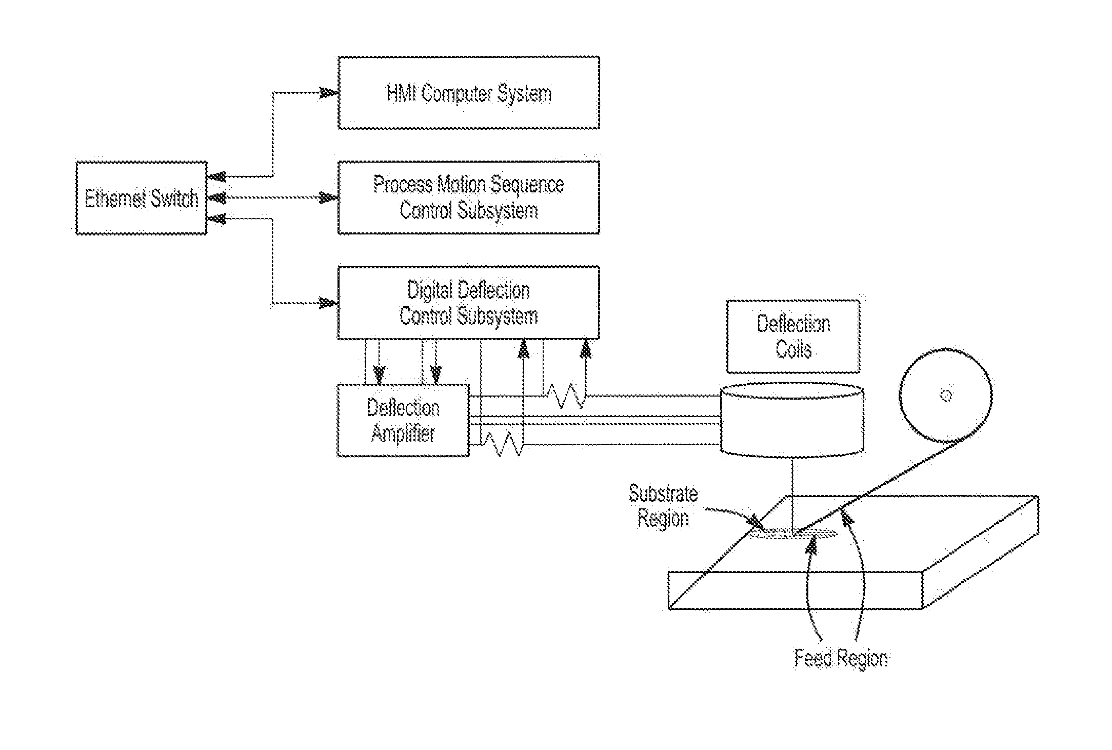
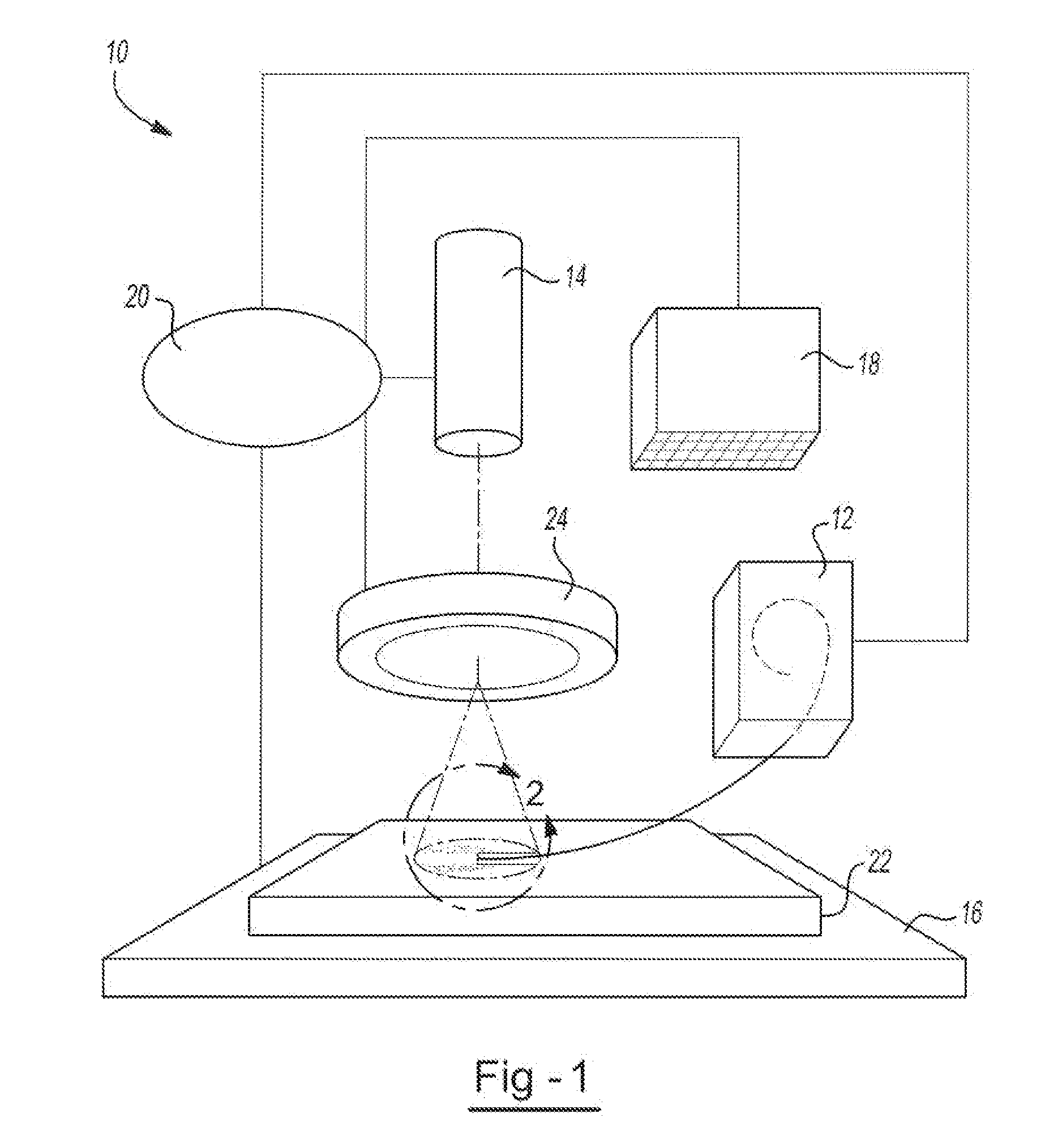
[0014]In this regard, the invention may be further characterized by one or any combination of the following features such as that the step of delivering the metallic feed material may include advancing a metallic wire feed at a substantially constant feed rate. The step of emitting an electron beam during successively repeating steps may include emitting a beam using a substantially constant clock rate throughout the repeating steps. Any translating of the electron beam may include deflecting the beam (e.g., with one or more electromagnetic coils). The translating step may include translating from point to point at a substantially constant clock rate. Throughout the steps a substantially constant frame rate may be employed. A substantially constant frame rate of at least about 1 kHz (e.g., about 1.4 kHz) may be employed, a clock ra...

Problems solved by technology

The second condition, however, is not readily predictable, as it will depend upon the amount of material that is deposited; the amount of material that has solidified (in contrast with that which is in a liquid state); the geometry of the resulting workpiece (inasmuch as that will affect the heat transfer and / or thermal mass characteristics of the workpiece); and other considerations that are continually changing in the course of material deposition.

Method used


Image

  • Raster methodology, apparatus and system for electron beam layer manufacturing using closed loop control
  • Raster methodology, apparatus and system for electron beam layer manufacturing using closed loop control
  • Raster methodology, apparatus and system for electron beam layer manufacturing using closed loop control

Examples


Embodiment Construction

[0020]As used herein, unless otherwise stated, the following terms have the following meanings:

[0021]The term “point” shall refer to a target location for a beam.

[0022]The phrase “raster pattern” shall refer to a two dimensional (x-y) scan pattern of points over which a beam is manipulated.

[0023]The term “frame” shall refer to a single complete cycle performed by a raster scan of a beam in order to complete a single entire raster pattern.

[0024]The phraseframe rate” shall refer to the rate at which a frame is executed.

[0025]The phraseclock rate” shall refer to the rate at which consecutive points are realized by the beam.

[0026]The phrase “point density” shall refer the number of points per unit area.

[0027]The phrase “power density” shall refer to an amount of power that is distributed to a unit area from the beam.

[0028]The present teachings are premised upon improvements in an apparatus and process for layer manufacturing (LM) of a three-dimensional article. The invention is part...


PUM

PropertyMeasurementUnit
Timeaaaaaaaaaa
Frequencyaaaaaaaaaa
Frequencyaaaaaaaaaa

Abstract

A method for layer-by-layer manufacturing of a three-dimensional metallic work piece, comprising the steps of: delivering a metallic feed material in a substantially solid state into a feed region; emitting an electron beam having one or more predetermined electrical currents; translating the electron beam through a first predetermined raster pattern frame in an x-y plane that includes: a plurality of points within the feed region sufficient so that the metallic feed material is subjected to a melting beam power density level sufficient to cause melting of the metallic feed material and formation of a molten pool deposit; and a plurality of points in a substrate region that is outside of the feed region, sufficient so that the plurality of points outside the feed region is subjected to a substrate beam power density level that is different from (e.g., lower than) the melting beam power density level; monitoring a condition of one or both of the feed region or the substrate region substantially in real time for the occurrence of any deviation from a predetermined condition; upon detecting of any deviation, translating the electron beam through at least one second predetermined raster pattern frame in the x-y plane that maintains the melting beam power density level substantially the same as the first predetermined raster pattern frame, but alters the substrate beam power density level in a manner so that the monitored condition returns to the predetermined condition; and repeating the above steps at one or more second locations for building up layer by layer, generally along a z-axis that is orthogonal to the x-y plane, a three-dimensional layered metallic work piece. The teachings herein also contemplate an apparatus that includes an electronic control device that performs any of the methods herein, as well as articles made according to such methods.

Description

CLAIM OF BENEFIT OF FILING DATE[0001]The present application claims the benefit of the filing date of U.S. Provisional Application No. 61 / 319,365, filed Mar. 31, 2010, the contents of which are hereby expressly incorporated by reference.FIELD OF THE INVENTION[0002]The present invention relates generally to layer manufacturing of articles and, more specifically, to additive manufacturing, direct manufacturing or solid freeform fabrication of articles using an electron beam gun.BACKGROUND OF THE INVENTION[0003]Free form fabrication (FFF), direct manufacturing (DM), and additive manufacturing (AM) are names for a general class of layer manufacturing (LM), in which a three-dimensional (3-D) article is made by the sequential build-up of layers of material. One or more suitable LM techniques may be utilized for making articles, (e.g., such as by creating one or more device patterns directly on a substrate). The LM technique usually includes a step of selectively depositing material layer ...

Claims


Application Information

Patent Timeline
IPC IPC(8): B23K15/00
CPCB23K15/0086B23K15/06B23K15/02B23K26/34B23K15/00B33Y70/00B23K2103/14B33Y10/00C22C14/00B23K26/346B23K26/342B33Y50/02B23K15/0093H01J37/3007H01J37/304H01J37/305
Inventor STECKER, SCOTTWOLLENHAUPT, PHILLIP E.
Owner SCIAKY SA
Learn More