
Arc welding control method

a control method and control method technology, applied in the direction of arc welding apparatus, manufacturing tools, welding apparatus, etc., can solve the problem of unstable welding state and other times, and achieve the effect of stably performing

Active Publication Date: 2017-02-09
DAIHEN CORP
View PDF15 Cites 0 Cited by
  • Summary
  • Abstract
  • Description
  • Claims
  • Application Information

AI Technical Summary

Benefits of technology

The present invention allows for a suppression of variations in the phase of the feeding rate when a short circuit occurs, which reduces the cycle of short circuits and arcs. By adjusting the value of the first welding current and / or conduction period, the length of the arc period can be controlled, resulting in stable welding.

Problems solved by technology

However according to this control, as the cycle of the feeding rate is changed by its own control, the welding state sometimes falls in an unstable state.

Method used


Image

  • Arc welding control method
  • Arc welding control method
  • Arc welding control method

Examples


first embodiment

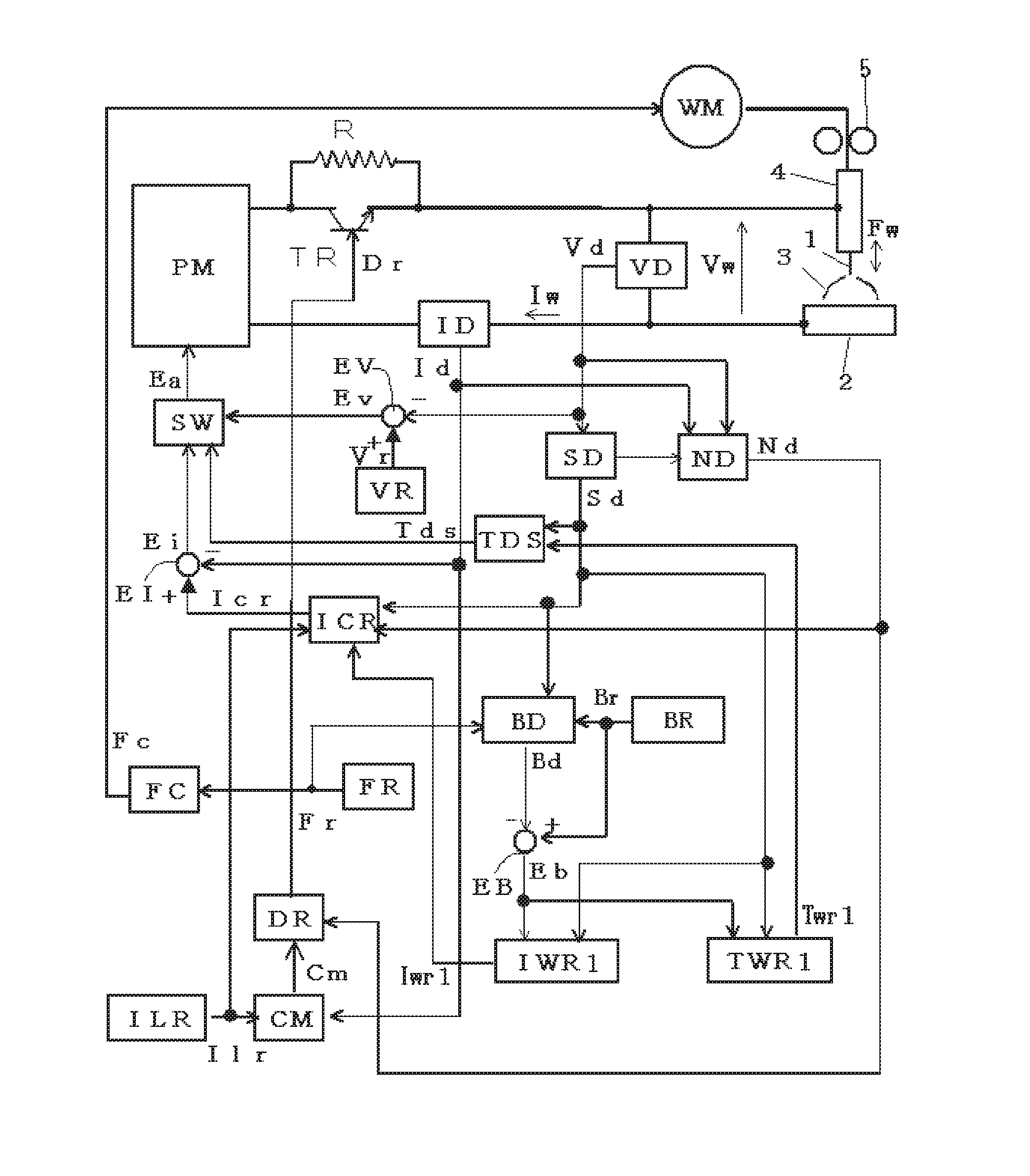
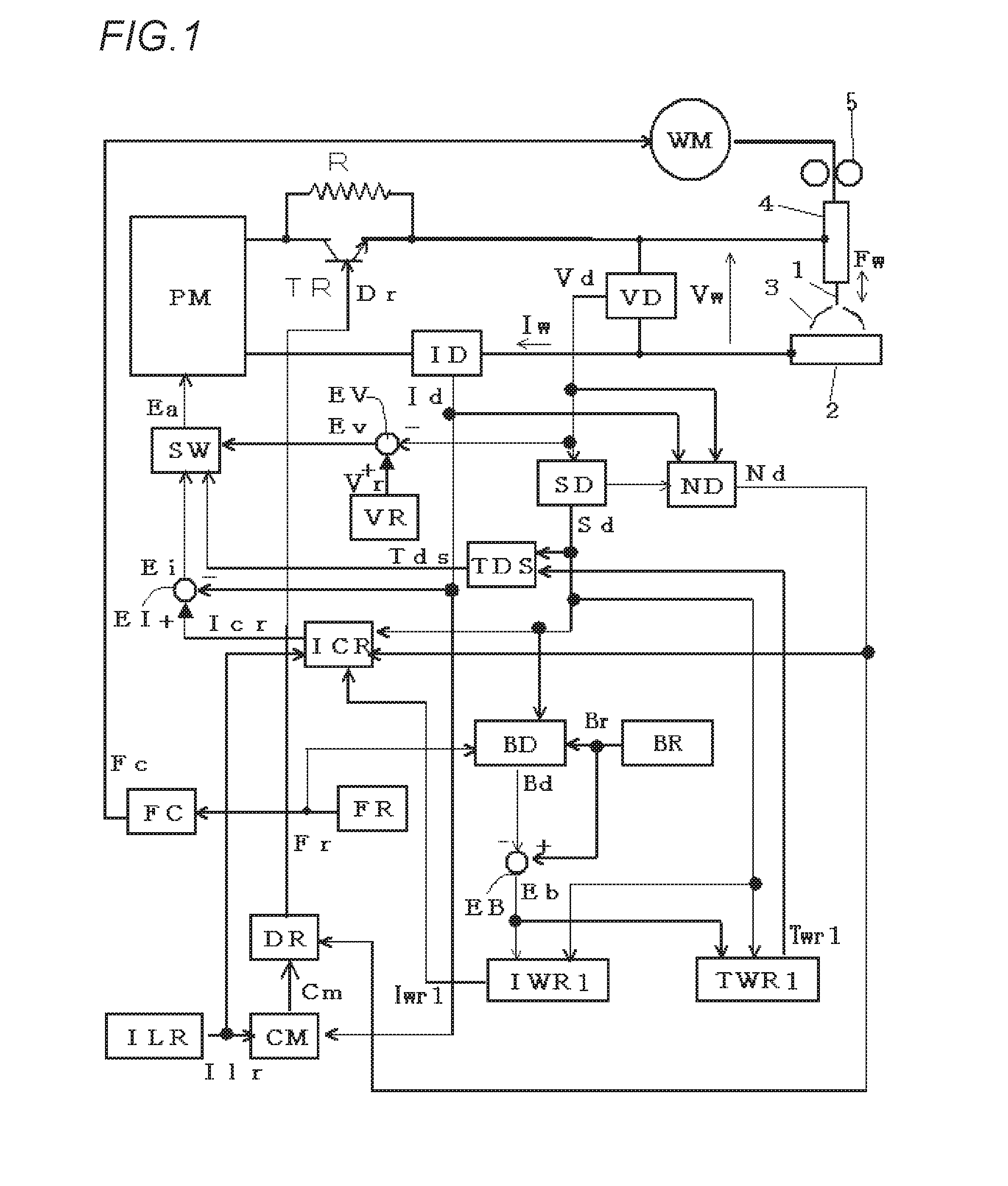
[0025]FIG. 1 is a block diagram illustrating a welding power supply for implementing an arc welding control method according to a first embodiment of the present invention. Hereinafter individual blocks will be explained with reference to this figure.

[0026]Using a power of three-phase 200V or the like from a commercial power supply (not shown) as input, a power supply main circuit PM subjects the input power to an output control such as an inverter control according to an error amplified signal Ea described later, and outputs a welding voltage Vw and a welding current Iw. Although not shown in the figure, this power supply main circuit PM includes a primary rectifier for rectifying the commercial power supply, a smoothing capacitor for smoothing the rectified DC, an inverter circuit for converting the smoothed DC into a high-frequency AC, a high-frequency transformer for stepping down the high-frequency AC to a voltage value suitable for welding, a secondary rectifier for rectifying...


PUM

PropertyMeasurementUnit
timeaaaaaaaaaa
timeaaaaaaaaaa
timeaaaaaaaaaa

Abstract

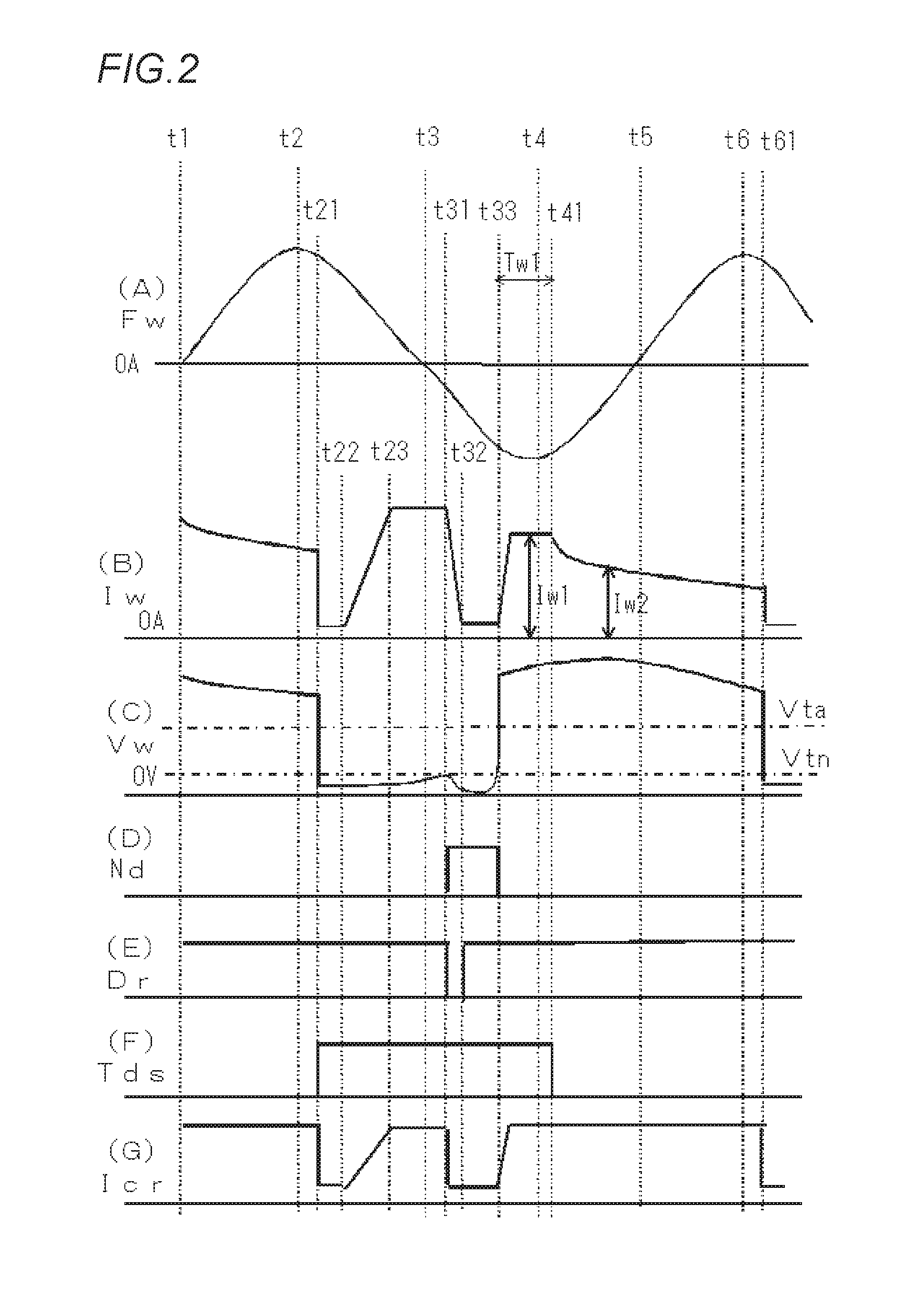
The present invention improves the stability of welding conditions in a welding method that involves cyclically repeating forward feed and reverse feed of a welding wire. Provided is an arc welding control method involving cyclic repetition of forward feed and reverse feed of a welding wire at feed speed, generating short-circuit intervals and arc intervals, during which arc intervals, application of a first welding current is followed by application of a second welding current smaller than the first welding current, wherein the phase of the feed speed at the point in time of transition from an arc interval to a short-circuit interval is detected, and the value and / or the application duration of the first welding current is varied in accordance with the detected phase. In so doing, fluctuation of the phase of the feed speed due to outside disturbances during generation of short-circuiting can be minimized.

Description

TECHNICAL FIELD[0001]The present invention relates to an arc welding control method of alternating feeding of a welding wire between forward feeding and reverse feeding as to a feeding rate cyclically to generate short-circuiting periods and arc periods and, during the arc period, flowing a second welding current smaller than a first welding current after flowing the first welding current.BACKGROUND ART[0002]In a typical consumable electrode arc welding, welding is performed by feeding a welding wire as a consumable electrode at a constant feeding rate and generating an arc between the welding wire and base material. In the consumable electrode arc welding, both the welding wire and the base material are mostly placed in a welding state in which a short circuit state and an arc generation state are alternately repeated.[0003]In order to further improve welding quality, there has been proposed a welding method of alternating feeding of a welding wire between forward feeding and rever...

Claims


Application Information

Patent Timeline
Patent Type & Authority Applications(United States)
IPC IPC(8): B23K9/12B23K9/095B23K9/073B23K9/09
CPCB23K9/12B23K9/073B23K9/095B23K9/09B23K9/092B23K9/0956B23K9/0953B23K9/173
Inventor IDE, AKIHIRO
Owner DAIHEN CORP
Learn More