
Integrated aircraft

a technology of integrated aircraft and jet engines, which is applied in the direction of rigid airships, aircraft navigation control, gas turbine type power plants, etc., can solve the problems low exhaust jet velocity of jet engines, and achieve low exhaust jet velocity and high propulsive efficiency. , the effect of high mass flow ra

Inactive Publication Date: 2011-10-06
KEHAYAS NIKOLAOS
View PDF8 Cites 7 Cited by
  • Summary
  • Abstract
  • Description
  • Claims
  • Application Information

AI Technical Summary

Benefits of technology

[0006]A jet that will provide the thrust needed to propel the aircraft, satisfy the condition for maximum lift-to-drag ratio, and be as close to the aircraft speed for high propulsive efficiency, must have a velocity much lower than the velocity of the exhaust jet of typical turbofans. As a result, jet engines with very low exhaust jet velocity, and, consequently, very-high mass flow rate are required. Selecting a very-high bypass ratio and lowering the combustion temperature of a geared turbofan make possible nearly equal values of total pressure for the cold and the hot streams, a jet engine nozzle pressure ratio less than the critical and, in turn, jet velocity less than Mach 1 at the jet engine nozzle. This jet engine nozzle velocity is low due to the low jet temperature arising from the mixing of the very-high bypass cold flow with the hot core flow. By being subsonic it can be further reduced with the use of a subsonic diffuser in the form of a fishtail duct.
[0007]Therefore, a jet aircraft designed as presented and characterized herein offers superior performance in cruising conditions as well as in take-off and landing.

Problems solved by technology

As a result, jet engines with very low exhaust jet velocity, and, consequently, very-high mass flow rate are required.

Method used


Image

  • Integrated aircraft
  • Integrated aircraft

Examples


Embodiment Construction

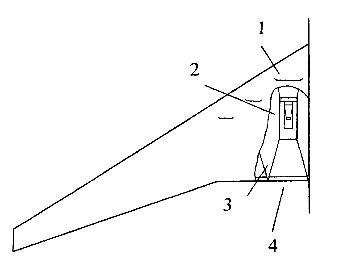
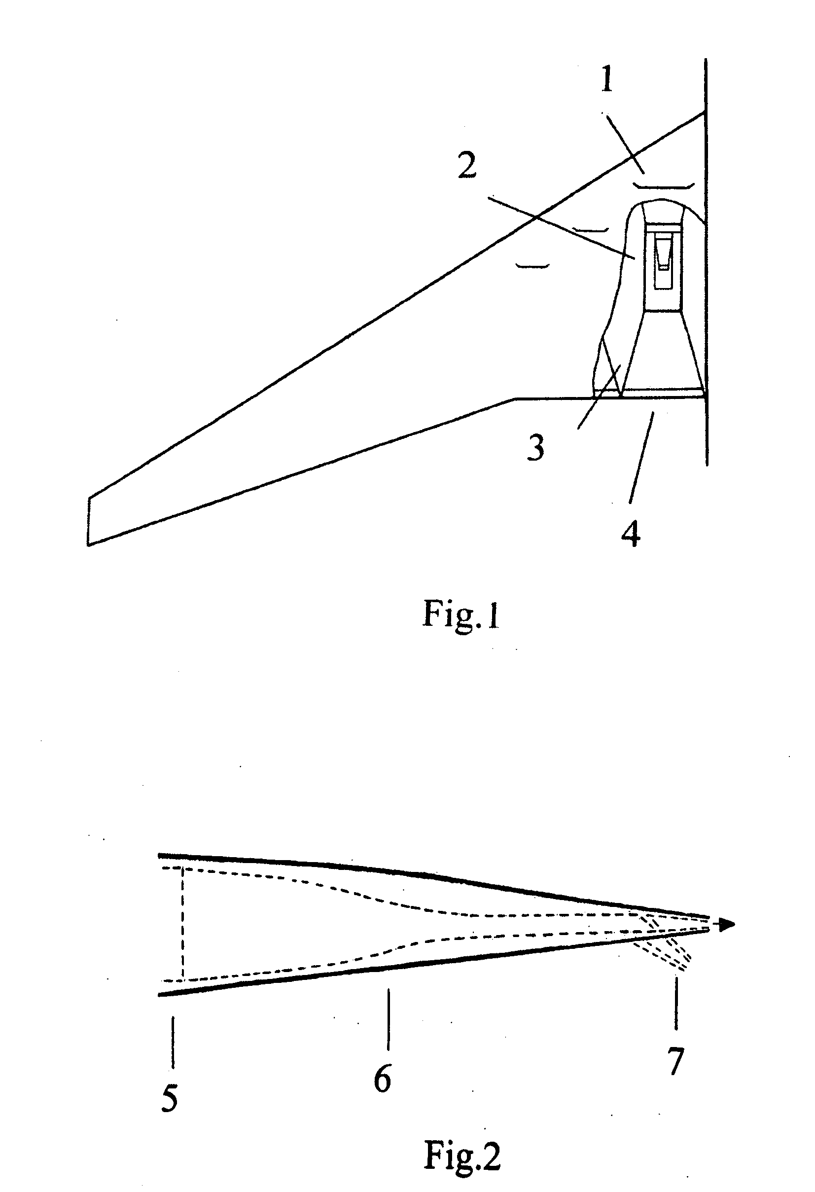
[0011]A jet aircraft, as schematically shown in FIGS. 1 and 2, incorporating a number of jet engines embedded in the wings 2, exhausting through fishtail diffuser ducts 3, from high aspect ratio two-dimensional nozzles located at a small control flap 4 at the trailing edge. The jet engines are positioned chordwise between the two wing spars 2. The engines are geared turbofans with a very-high bypass ratio and an operating temperature lower than typical, such that the exhaust nozzle flow is not choked. The engines air intakes 1 are situated in the upper surface of the wing. Inlet, s shape, ducts connect the air intakes to the engines.

[0012]The jet arising from the geared turbofan 5 and diffuser duct 6 combination has a velocity that provides towards the required thrust, satisfies the condition for maximum lift-to-drag ratio of the jet-flapped wings in cruising conditions and is close to the aircraft speed. The number of the embedded geared turbofans is a function of turbofan diameter...


PUM


Abstract

In a jet aircraft according to the invention the jet engines are embedded in the wings and exhaust through fishtail diffuser ducts, from high aspect ratio nozzles located at a small control flap at the wing trailing edge. The jet engines are very-high bypass ratio geared turbofans operating at a lower than typical temperature. The jet aircraft according to the invention exhibits exceptionally low zero-lift drag leading to exceptionally high lift-to-drag ratios.

Description

[0001]I claim the benefit of Provisional Application No 61 / 282,797 filed on 1 Apr.2010 and entitled “Integrated aircraft”BACKGROUND OF THE INVENTION[0002]Since the late 1950s subsonic civil transport aircraft technology has advanced substantially. This advance has been evolutionary and, consequently, the basic aircraft configuration has remained unchanged. It has been suggested that the conventional aircraft configuration is nearing its full evolutionary potential and a departure in the form of a new configuration or technology, or a combination of both, is needed. As a result a number of alternative concepts have been put forward, such as the blended wing-body, non-planar wings, laminar flow control, unducted fan and powered lift. The invention relates to a powered lift design based on the jet flap concept in combination with a very-high bypass ratio geared turbofan operating at a lower than typical temperature. The combination leads to an-exceptionally high lift-to-drag ratio.[000...

Claims


Application Information

Patent Timeline
Patent Type & Authority Applications(United States)
IPC IPC(8): B64D27/12
CPCB64D33/04B64D27/18
Inventor KEHAYAS, NIKOLAOS
Owner KEHAYAS NIKOLAOS
Learn More