Wireless power transmission system

Active Publication Date: 2011-10-06
PANASONIC CORP
View PDF2 Cites 132 Cited by
  • Summary
  • Abstract
  • Description
  • Claims
  • Application Information

AI Technical Summary

Benefits of technology

[0025]In yet another preferred embodiment, the series resonant circuit is prevented from contributing to power transfer by turning every one of the switches ON.
[0026]In an alternative preferred embodiment, the series resonant circuit is prevented from contributing to power transfer by turning every one of the switches OFF.
[0027]In yet another preferred embodiment, the wireless power transmission system includes a power transmitter for supplying power to the power-transmitting resonator through the power supplying structure. And the optimum input impedance of the power-transmitting reso

Problems solved by technology

Nevertheless, since the coupling coefficient is low (k≠1), high-efficiency energy transfer cannot be realized unless impedance matching is maintained between the power transmitter and the power transmitting resonator, and between the power receiver and the power receiving resonator, which i

Method used


Image

  • Wireless power transmission system
  • Wireless power transmission system
  • Wireless power transmission system

Examples


embodiment 1

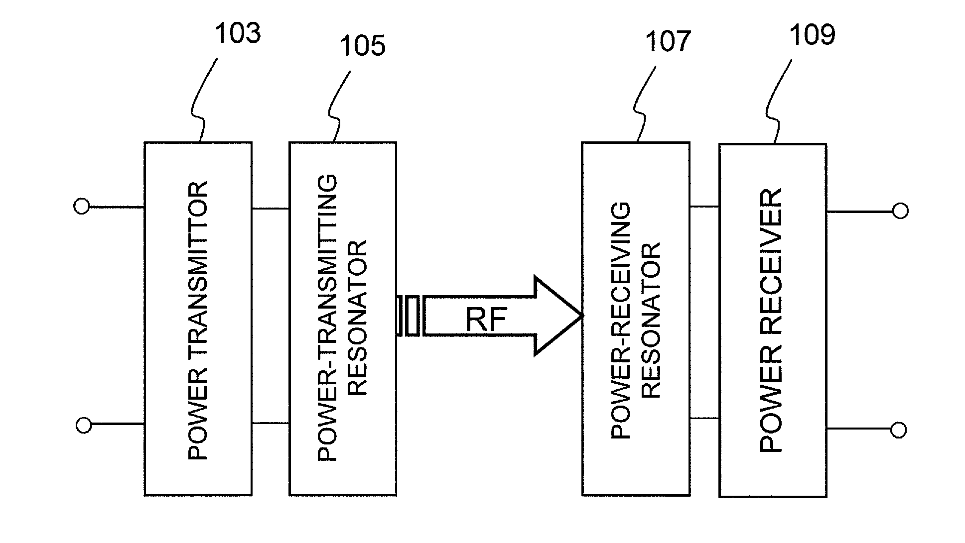
[0045]FIG. 1 is a block diagram illustrating a configuration for a wireless power transmission system as a first specific preferred embodiment of the present invention.

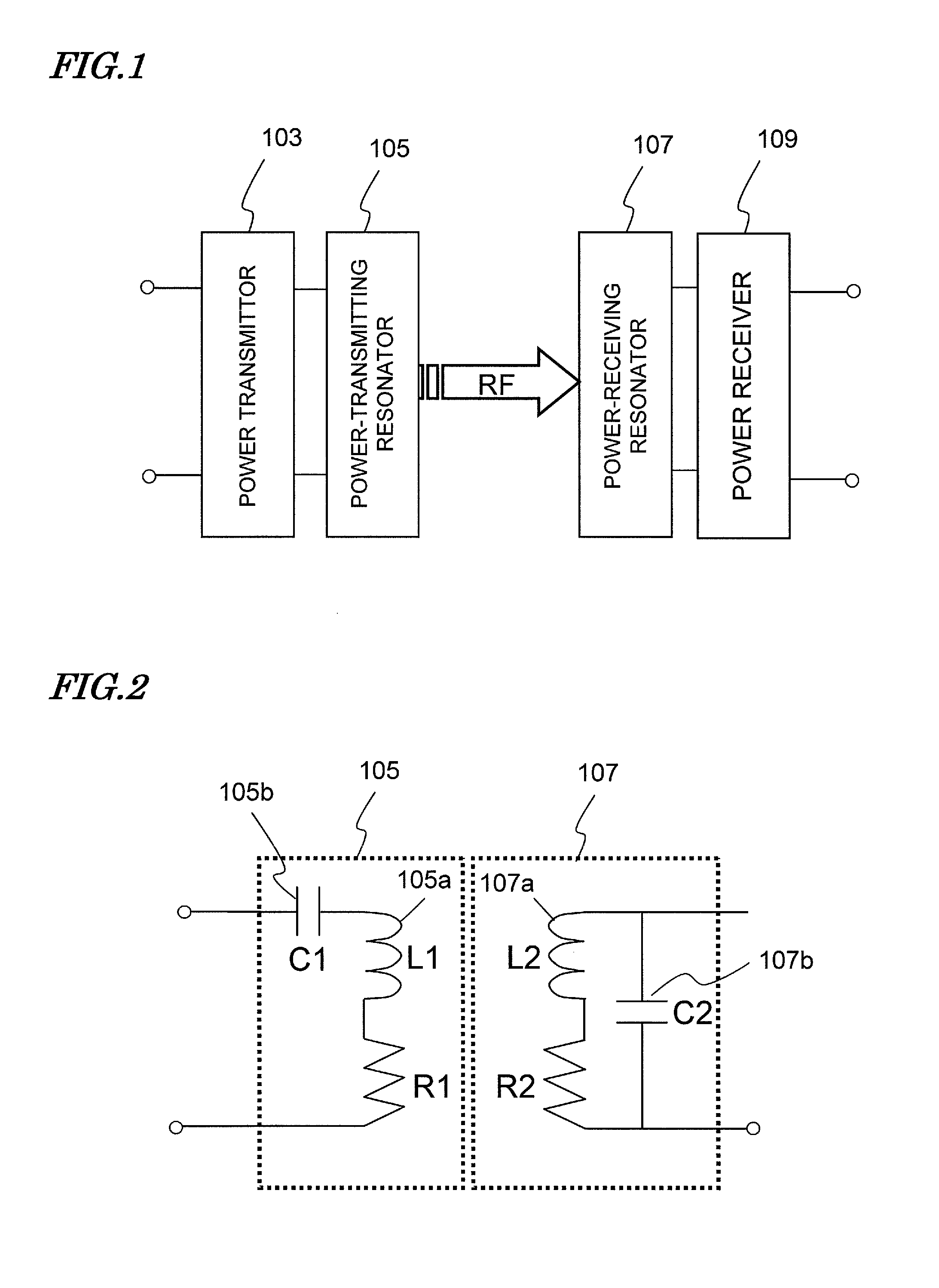
[0046]As shown in FIG. 1, the Wireless Power Transmission system of this preferred embodiment includes a power-transmitting resonator 105 and a power-receiving resonator 107 and transmits power between the power-transmitting resonator 105 and the power-receiving resonator 107 over a resonant magnetic field. This wireless power transmission system is designed so that the power-transmitting resonator 105 and the power-receiving resonator 107 set up resonances at a frequency f0.

[0047]A power transmitter 103 is connected to the power-transmitting resonator 105. The power transmitter 103 receives DC or AC energy (electric energy) from a power supply (not shown) and transforms the energy into RF energy with the frequency f0. The RF energy is sent out from the power transmitter 103 to the power-transmitting resonator 105. Th...

embodiment 2

[0092]Hereinafter, a second preferred embodiment of a wireless power transmission system according to the present invention will be described with reference to FIG. 8. The only difference between this second preferred embodiment and the first preferred embodiment described above is the arrangement of the impedance variable series resonant circuit. That is why the following description of this second preferred embodiment will be focused on the arrangement of the series resonant circuit and description of the other arrangements will be omitted herein to avoid redundancies.

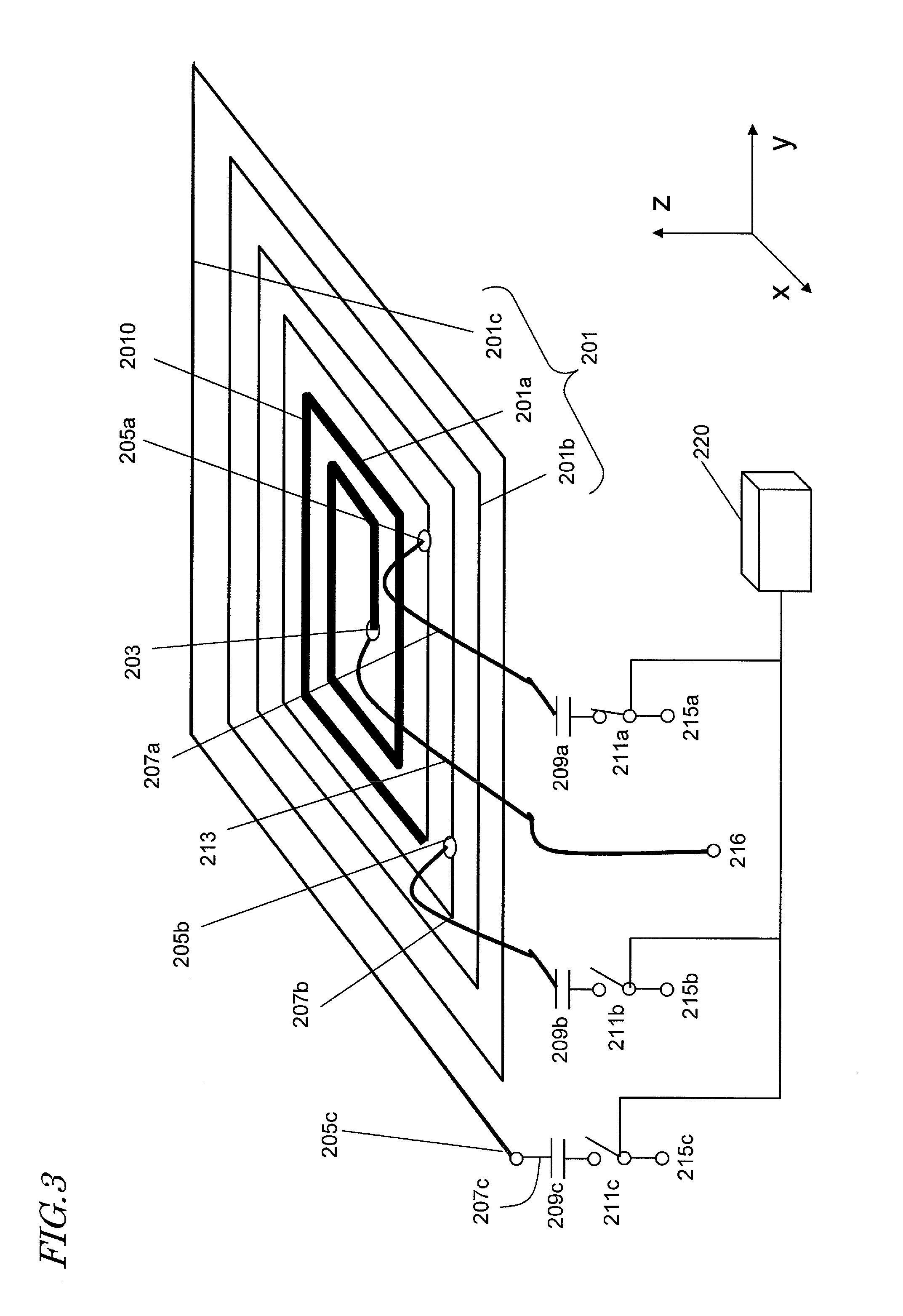
[0093]In the preferred embodiment illustrated in FIG. 3, the signal-side extended wire 213 to be directly connected to the external terminal 216 is connected to a terminal inside the spiral of the spiral wiring 201. On the other hand, according to this second preferred embodiment, the signal-side extended wire 213 is connected to a terminal that is located outside of the spiral of the spiral wiring 201 as shown in FI...

embodiment 3

[0096]Hereinafter, a third preferred embodiment of a wireless power transmission system according to the present invention will be described with reference to FIG. 9. The only difference between this third preferred embodiment and the preferred embodiments described above is the arrangement of the impedance variable series resonant circuit. That is why the following description of this third preferred embodiment will be focused on the arrangement of the series resonant circuit and description of the other arrangements will be omitted herein to avoid redundancies.

[0097]In the variable resonators shown in FIGS. 3 and 8, switching circuits that make any one of the current paths selectable are provided for only the ground-side extended wires. On the other hand, according to this third preferred embodiment, another switching circuit is also provided for the signal-side extended wire as shown in FIG. 9. Specifically, two signal input terminals 216a and 216b are selectively connected to tw...


PUM


Abstract

The wireless power transmission system of this invention transmits power over a resonant magnetic field. The system includes a power-transmitting resonator 105 and a power-receiving resonator 107, at least one of which is a series resonant circuit with an inductor including spiral wiring 201 and extended wires 213, 207a, 207b and 207c. The extended wire 213 connects a point 203 of the spiral wiring 201 to a power supplying structure, while the extended wires 207a, 207b and 207c connect other points of the spiral wiring 201 to the power supplying structure. Capacitors 209a, 209b and 209c and switches 211a, 211b and 211c are connected to the extended wires 207a, 207b and 207c, respectively. The series resonant circuit has its inductance varied according to which current path has been chosen by selectively turning ON one of the switches. A wiring portion 201a of the spiral wiring 201 has a low-resistance portion 2010, of which the wiring resistance per unit length at a resonant frequency is set to be lower than in at least a part of the rest of the spiral wiring.

Description

[0001]This application claims priority under 35 USC §119(e) to U.S. Provisional Application No. 61 / 318,807 filed on Mar. 30, 2010, the entire contents of which are incorporated herein by reference.BACKGROUND OF THE INVENTION[0002]1. Field of the Invention[0003]The present invention relates to a wireless power transmission system for transferring energy in order to charge a device with electric power or supply or collect electric power to / from a device and also relates to a wireless power transmission unit for use in such a system.[0004]2. Description of the Related Art[0005]Wireless energy transfer technologies have attracted increasing attention these days in order to increase the mobility and water resistance of various electronic devices as much as possible; realize a wireless wall-mounted TV monitor; and charge and supply power to a big moving object such as an electric vehicle.[0006]As a novel non-contact power transmission method that would replace the conventional one that us...

Claims


Application Information

Patent Timeline
IPC IPC(8): H01F38/14
CPCH01F21/12H01F38/14H02J5/005H02J17/00Y02B70/1441H01F21/00H02M2007/4818H02J50/12Y02B70/10H02M7/4818
Inventor KANNO, HIROSHI
Owner PANASONIC CORP
Why Eureka
Try Eureka