System and method of parallel imaging for magnetic resonance imaging near metallic implants

Active Publication Date: 2011-10-06
GENERAL ELECTRIC CO
View PDF2 Cites 22 Cited by
  • Summary
  • Abstract
  • Description
  • Claims
  • Application Information

AI Technical Summary

Benefits of technology

[0009]It would therefore be desirable to have a system and method capable of p

Problems solved by technology

Accordingly, these materials can introduce distortions in the main magnetic field resulting in an inhomogeneous magnetic field.
While the signal loss induced by these field gradients can largely be regained through the use of Hahn spin-echoes, the distortion they produce in both the readout and slice directions are drastic and are typically unacceptable for clinical evaluation.
Unfortunately, artifacts induced by the implants in conventional MRI images are most severe near the implant interfaces.
However, a drawback of the MAVRIC technique is its prolonged scan time, which can reach upwards of 20-25 minutes under common circumstances.
However, SENSE

Method used


Image

  • System and method of parallel imaging for magnetic resonance imaging near metallic implants
  • System and method of parallel imaging for magnetic resonance imaging near metallic implants
  • System and method of parallel imaging for magnetic resonance imaging near metallic implants

Examples


Embodiment Construction

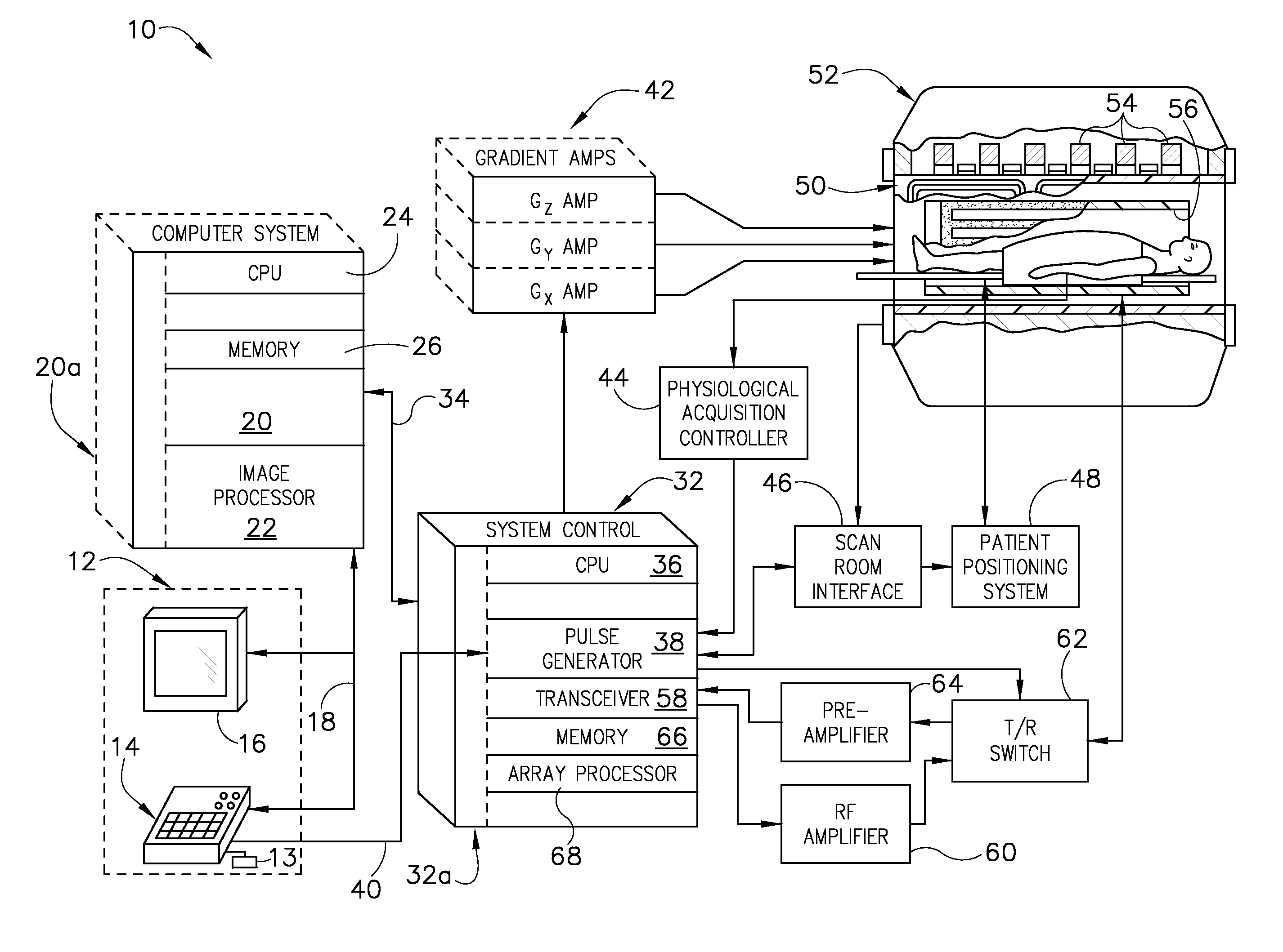
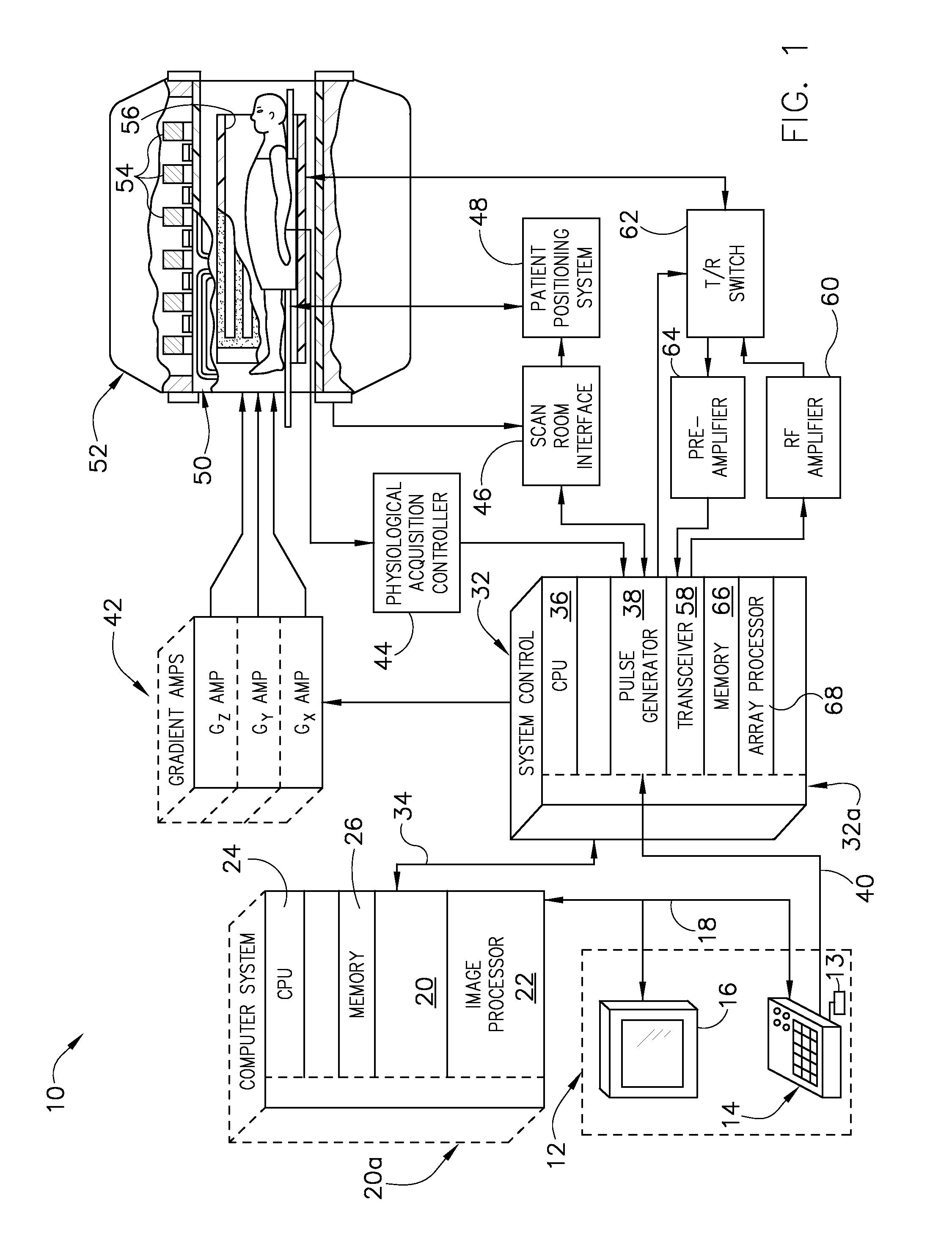
[0022]Referring to FIG. 1, the major components of a magnetic resonance imaging (MRI) system 10 incorporating an embodiment of the invention are shown. The operation of the system is controlled from an operator console 12 which includes a keyboard or other input device 13, a control panel 14, and a display screen 16. The console 12 communicates through a link 18 with a separate computer system 20 that enables an operator to control the production and display of images on the display screen 16. The computer system 20 includes a number of modules which communicate with each other through a backplane 20a. These include an image processor module 22, a CPU module 24 and a memory module 26, which may include a frame buffer for storing image data arrays. The computer system 20 communicates with a separate system control 32 through a high speed serial link 34. The input device 13 can include a mouse, joystick, keyboard, track ball, touch activated screen, light wand, voice control, or any s...


PUM


Abstract

A system and method for magnetic resonance imaging is disclosed, the MRI apparatus comprising a computer programmed to acquire a plurality of 3D MR data sets, each 3D MR data set acquired using a central transmit frequency and a central receive frequency set to an offset frequency value that is distinct for each 3D MR data set, wherein at least a portion of each 3D MR data set is accelerated k-space data, and wherein at least one of the plurality of 3D MR data sets comprises fully-sampled calibration k-space data lines. The computer is also programmed to determine reconstruction weights from the fully-sampled calibration k-space data lines, reconstruct an image for each 3D MR data set using the reconstruction weights from the fully-sampled calibration k-space data lines to synthesize unacquired data, and generate a composite image from the reconstructed images based on the plurality of 3D MR data sets.

Description

BACKGROUND OF THE INVENTION[0001]Embodiments of the invention generally to magnetic resonance (MR) imaging and, more particularly, MR imaging near metallic implants.[0002]When a substance such as human tissue is subjected to a uniform magnetic field (polarizing field Bo), the individual magnetic moments of the spins in the tissue attempt to align with this polarizing field, but precess about it in random order at their characteristic Larmor frequency. If the substance, or tissue, is subjected to a magnetic field (excitation field B1) which is in the x-y plane and which is near the Larmor frequency, the net aligned moment, or “longitudinal magnetization”, MZ, may be rotated, or “tipped”, into the x-y plane to produce a net transverse magnetic moment Mt. A signal is emitted by the excited spins after the excitation signal B1 is terminated and this signal may be received and processed to form an image.[0003]When utilizing these signals to produce images, magnetic field gradients (Gx, G...

Claims


Application Information

Patent Timeline
IPC IPC(8): G01R33/48
CPCG01R33/5611G01R33/285
Inventor CHEN, WEITIANBRAU, ANJA C. S.BEATTY, PHILIP JAMES
Owner GENERAL ELECTRIC CO
Why Eureka
Try Eureka