Display apparatus for displaying image

a technology of display apparatus and image, which is applied in the field of display apparatus for image, can solve the problems of difficulty in reducing power consumption, and achieve the effects of reducing power consumption, improving user's visibility of the mark, and reducing intensity

Inactive Publication Date: 2011-10-06
FUJITSU GENERAL LTD
View PDF11 Cites 1 Cited by
  • Summary
  • Abstract
  • Description
  • Claims
  • Application Information

AI Technical Summary

Benefits of technology

[0013]In a car navigation image, an external area other than an area within a predetermined range centered on a vehicle location mark is set to a black image, and a backlight is controlled so as to illuminate the black image with a lower intensity than an area including a mark. Thereby, it is possible to redu

Problems solved by technology

However, basically in the case where a specific image that is comprised of illustrations having few low-brightness areas is displayed

Method used


Image

  • Display apparatus for displaying image
  • Display apparatus for displaying image
  • Display apparatus for displaying image

Examples


embodiment

Representative Embodiment

[0028]

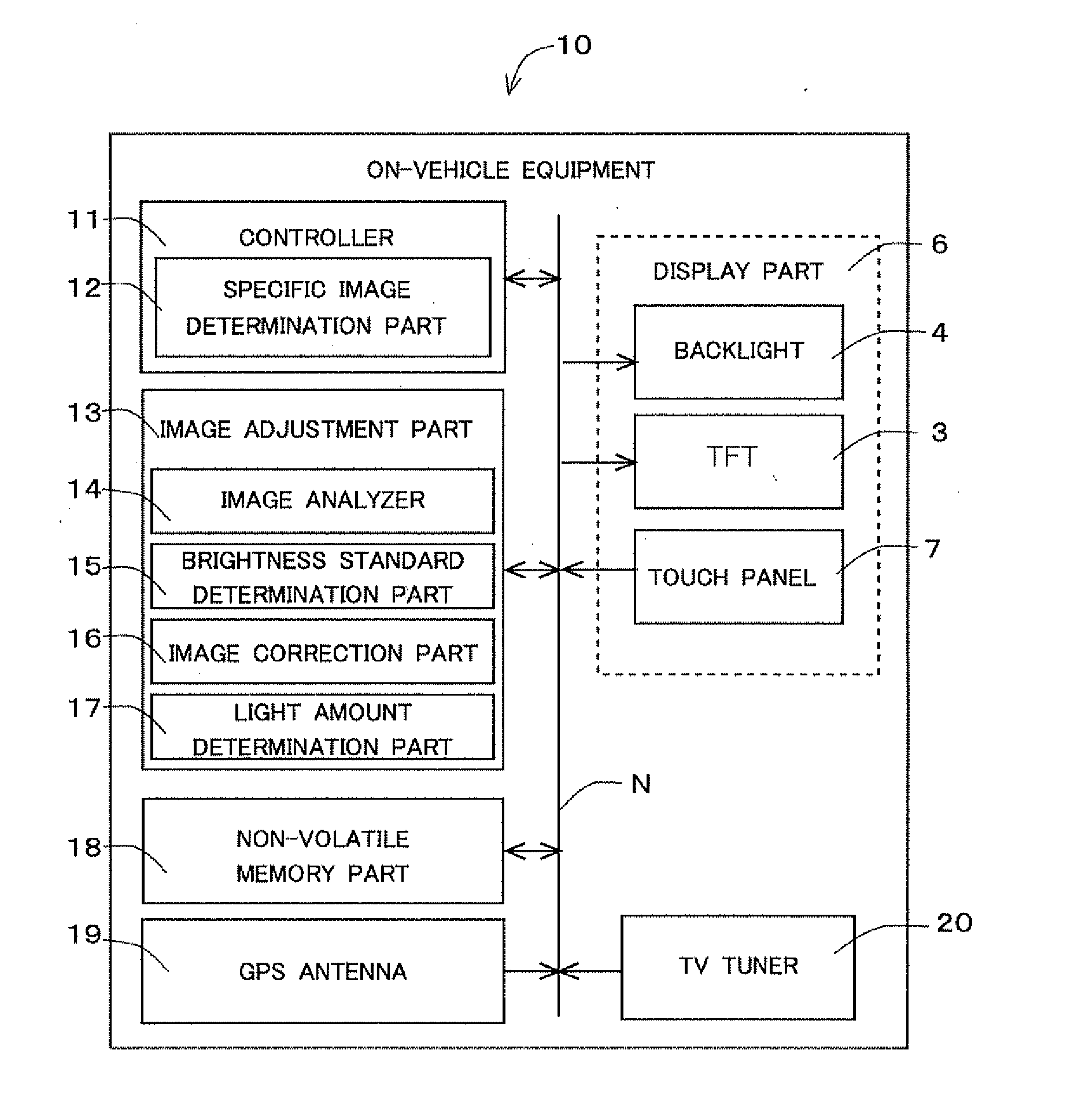
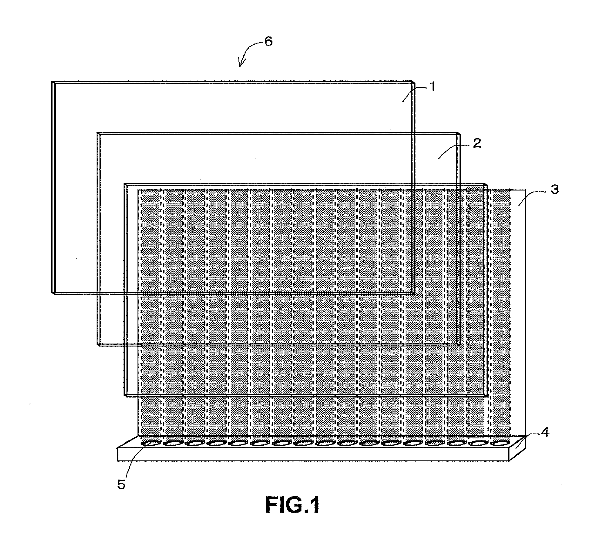
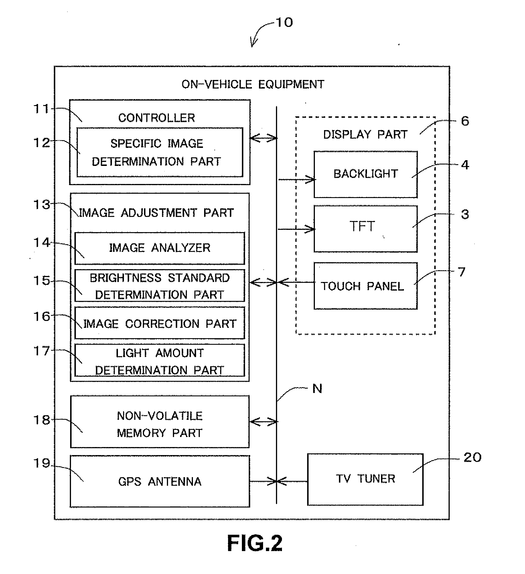
[0029]A structure of a display part included in on-vehicle equipment to be installed on a vehicle is explained based on FIG. 1. A display part 6 includes a color filter 1, a liquid crystal layer 2, TFT (Thin Film Transistor) 3, a backlight 4, and the like.

[0030]The color filter 1 is a film on which three primary colors (RGB) are printed for each pixel. The liquid crystal layer 2 functions as a shutter that transmits light by changing its molecular array when voltage is applied. The TFT 3 is a thin-film transistor that transmits light of the backlight 4 to the color filter 1 side by controlling electrodes arrayed in a matrix pattern, applying voltage to an intended cell in the matrix pattern and then changing the molecular array of liquid crystal of the liquid crystal layer 2 corresponding to the intended cell. The backlight 4 includes a plurality of light emitting diodes (LED) 5 as light sources which are arrayed in line on one side of a rectangular di...

modification examples

[0069]Although the representative embodiment of this invention has been explained, this invention is not limited to the representative embodiment mentioned above, and various modifications are possible. Modification examples of the representative embodiment are explained below. Moreover, the modifications described below may be combined arbitrarily.

modification examples 1

[0070]In the representative embodiment described above, the external area S1 and the external area S2 are allocated outside of both sides (right and left side) of the navigation guidance area M. However, as shown in FIG. 6, it is acceptable to allocate the external area S3 outside of either one of left or right side of the navigation guidance area M. The image analyzer 14 sets the allocated external area S3 to a black image.

[0071]In this ease, as shown in FIG. 6, the light amount determination part 17 determines to turn on, in a certain amount of light emission, the LED 5A to LED 5M corresponding to the area M within a predetermined range in a car navigation image G3. In addition, the light amount determination part 17 determines not to turn on LED 5N to the LED 5U corresponding to the external area S3 on the car navigation image G3.

[0072]In the step SA7, as shown in FIG. 6, the controller 11 makes the LED 5A to the LED 5M emit light in a certain amount, which correspond to the area...


PUM


Abstract

A display apparatus for displaying an image determines whether or not an image to be displayed on a screen is a specific image including a mark. In the case where the display apparatus determines the image to be the specific image, the display apparatus controls a backlight so as to illuminate the screen so that areas other than an area including a mark on the specific image are illuminated with less brightness than the brightness of the area including the mark.

Description

BACKGROUND OF THE INVENTION[0001]1. Field of the Invention[0002]The invention relates to technologies for displaying an image on a screen.[0003]2. Description of the Background Art[0004]Recently, energy-saving technologies have become important against the background of environmental problems, and display apparatuses such as a television, a portable terminal, a personal computer, and a car navigation apparatus in which the energy-saving technologies are adopted attract attention.[0005]The energy-saving technologies that are adopted for such display apparatuses, for example, include a technology to significantly reduce power consumption by controlling a backlight effectively.[0006]This technology is explained more closely. A display apparatus turns on, in response to brightness of an image, each of a plurality of LEDs which comprise a backlight, corresponding to a display area of a display screen. Thereby, the display apparatus can turn off the LEDs corresponding to relatively dark a...

Claims


Application Information

Patent Timeline
IPC IPC(8): G09G5/10
CPCG09G3/3426
Inventor OHNISHI, KOHJI
Owner FUJITSU GENERAL LTD
Why Eureka
Try Eureka