Flexible modular assembly

a modular assembly and flexible technology, applied in the direction of electrical apparatus, printed circuits, electrical apparatus casings/cabinets/drawers, etc., can solve the problems of difficult mounting electronic components onto the textile, increasing the cost of picking and placing components, and achieving high conductivity

Inactive Publication Date: 2011-10-06
SIGNIFY HLDG BV +1
View PDF9 Cites 10 Cited by
  • Summary
  • Abstract
  • Description
  • Claims
  • Application Information

AI Technical Summary

Benefits of technology

[0014]The textile support can have electrically conductive yarns embroidered, stitched or woven into it with some pattern that allows for the supply of information (data) and/or power to contact points comprised on the

Problems solved by technology

Such an approach, however, has the disadvantage of becoming quickly costly and difficult to pick and place components on.
Since a textile is not a flat and rigid body, it is difficult to mount electronic components onto the textile in a sufficiently accurate way with a pick and place apparatus, especially for textiles with relatively large dimensions, such as, for instance, a textile with dimensions that exceed 0.5×0.5 square meter.
Furthermore, a problem found specifically with woven electronic textiles is that only certain types of electrically conductive yarns can be woven into the el

Method used


Image

  • Flexible modular assembly
  • Flexible modular assembly
  • Flexible modular assembly

Examples


Embodiment Construction

[0035]The present invention will now be described more fully hereinafter with reference to the accompanying drawings, in which certain embodiments of the invention are shown. This invention may, however, be embodied in many different forms and should not be construed as limited to the embodiments set forth herein; rather, these embodiments are provided by way of example so that this disclosure will be thorough and complete, and will fully convey the scope of the invention to those skilled in the art. Like numbers refer to like elements throughout.

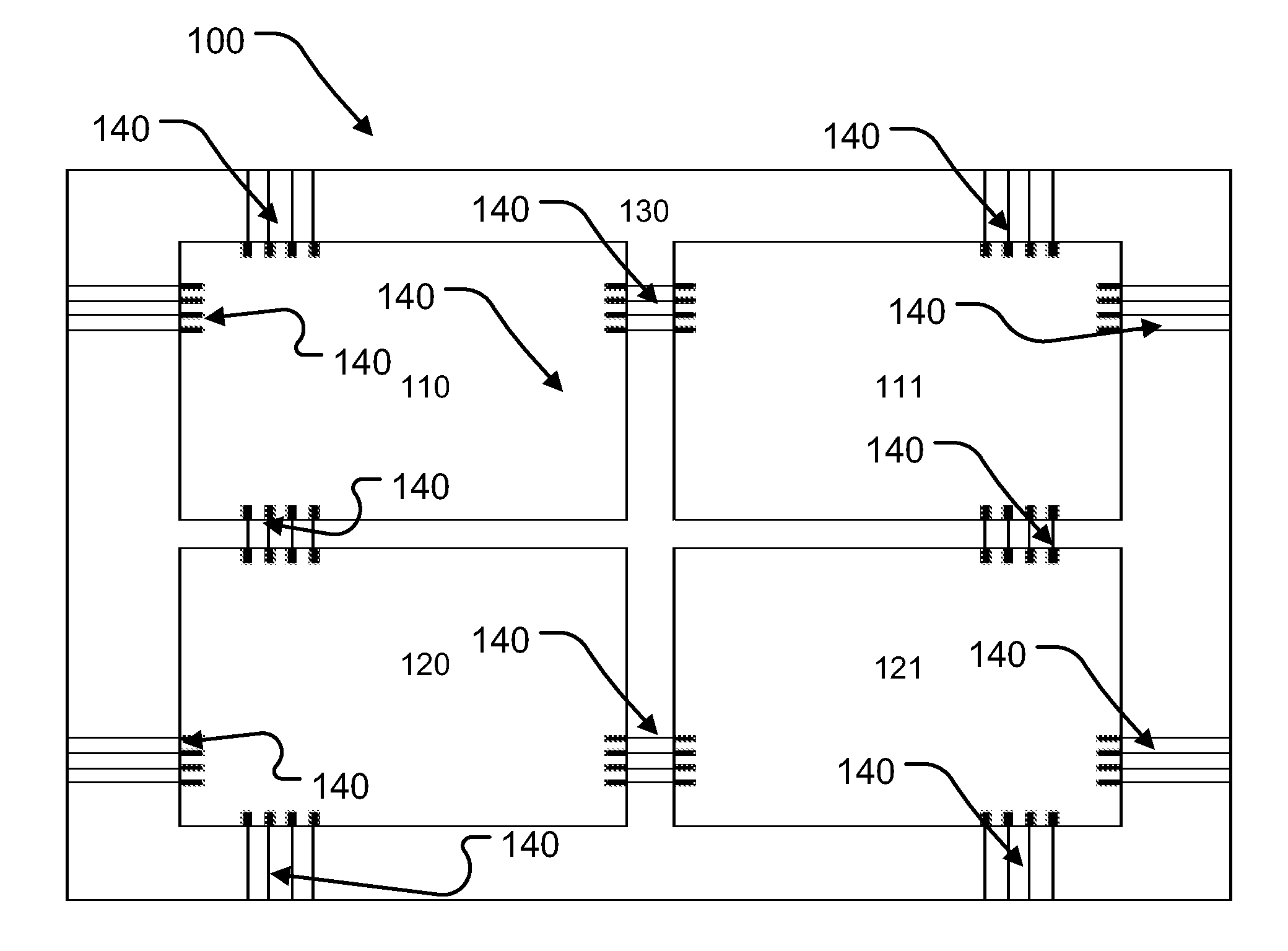
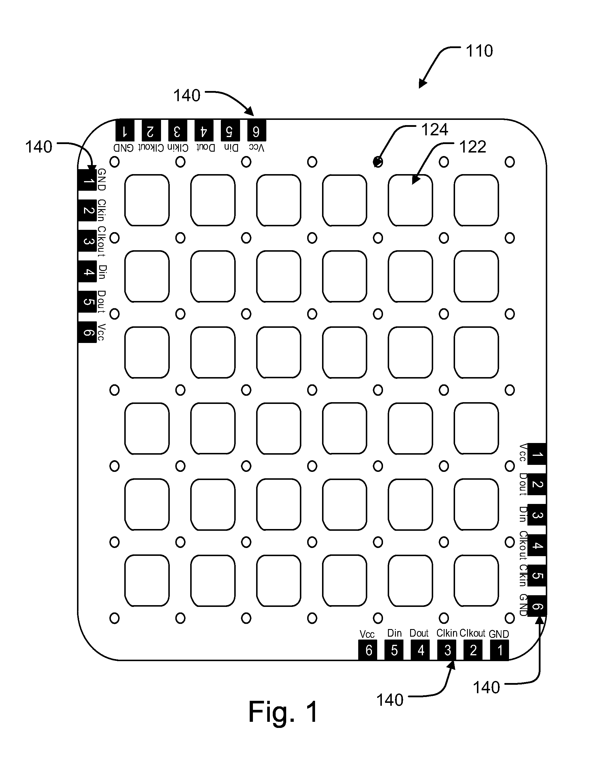
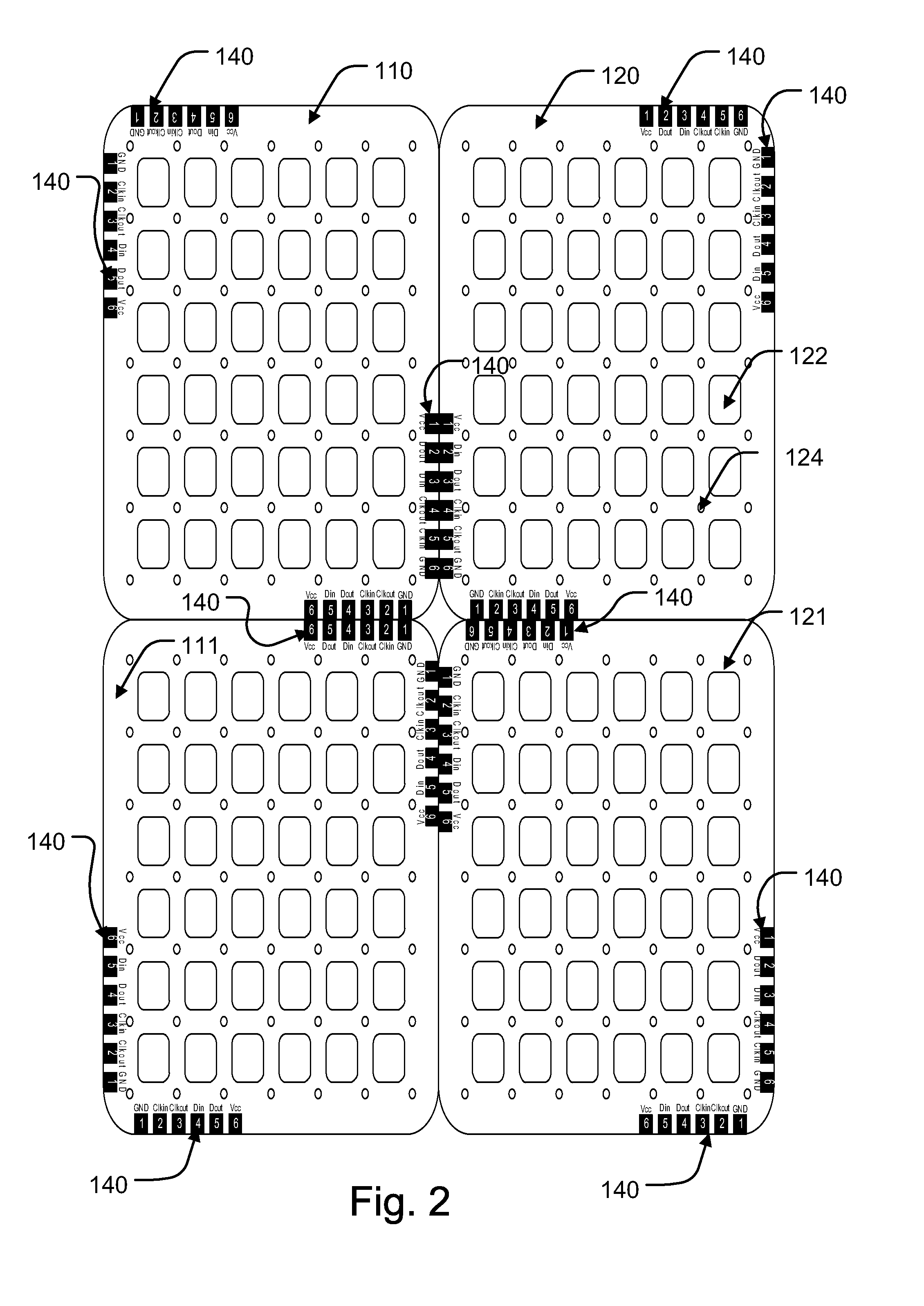
[0036]In general for FIGS. 1, 2, 3, 5 and 6 the reference numeral 140, though here shown referring to the contact pad, is intended to mean that the flexible electronic modules 110, 111, 120 and 121 can be adhered to the textile support 130 by a number of flexible connectors made by, for example, lamination, stitching, embroidering, soldering, gluing, clamping, double sided metal contacts, or any combination thereof. Stitching means and embr...


PUM

PropertyMeasurementUnit
Flexibilityaaaaaaaaaa

Abstract

The present invention relates to a flexible modular assembly (100) comprising at least two flexible electronic modules (110 and 111) supported by a textile support (130). The two flexible electronic modules and the textile support each comprise a set of electrical conductors. The flexible modular assembly further comprises flexible connectors (140) for interconnecting two sets of electrical conductors. The flexible modular assembly of the invention is a modular textile assembly for use in large-area applications of electronic textiles.

Description

FIELD OF THE INVENTION[0001]The present invention relates to a flexible modular assembly, in particular to a flexible modular assembly comprising electronic textiles, and to a method of manufacturing the flexible modular assembly.BACKGROUND OF THE INVENTION[0002]A textile is a material comprised of a network of fibres, that can for instance be manufactured by weaving, knitting, crocheting, knotting, or pressing fibres together. For this purpose, interlocked fibres known as yarns or threads may be used.[0003]Many types of textiles are used in our every day life. When electronic components (i.e. devices that work by controlling the flow of electrons) are integrated into a textile new application fields emerge. When the textile is an integral part of the electrical circuit comprising the electronic components, an electronic textile is obtained.[0004]An example of an electronic component is a LED package in the form of a surface mounted device (SMD-LED), which can be attached to a texti...

Claims


Application Information

Patent Timeline
IPC IPC(8): H05K5/00H05K13/04
CPCH05K1/147H05K1/038H05K2201/029H05K2201/10106H05K1/189H05K1/142H05K1/141Y10T29/49128
Inventor BHATTACHARYA, RABINKRANS, MARTIJNVAN PIETERSON, LIESBETHSCHULER, THOMASLAMERICHS, GUIDOALTEWISCHER, ERWIN
Owner SIGNIFY HLDG BV
Why Eureka
Try Eureka