
Method for performing power headroom reporting procedure and phr mac control element

a power headroom and reporting procedure technology, applied in the field of power headroom reporting mechanism, can solve the problems of system capacity waste, signal to interference-plus-noise ratio (sinr) reduction, and the inability to efficiently distribute/allocate uplink transmission resources between multiple user equipments (ues)

Active Publication Date: 2011-10-06
HFI INNOVATION INC
View PDF8 Cites 193 Cited by
  • Summary
  • Abstract
  • Description
  • Claims
  • Application Information

AI Technical Summary

Benefits of technology

[0026]It is therefore a first objective of the present invention to provide a method for performing Power Headroom reporting procedure, so that the eNB can completely obtain the information of PHR for activated serving cells.
[0034]In the present invention, since the PHR is triggered and reported for all activated serving cells, the complete information of PHR for serving cells can be obtained by the eNB. When simultaneous transmission of Physical Uplink Control CHannel (PUCCH) and Physical Uplink Shared CHannel (PUSCH) on the same carrier is configured, the type 2 power headroom can be also transmitted with the type 1 power headroom so that the eNB can correctly allocate the resources to the user equipment according to the transmitted type 1 and type 2 PHR information. In the other respect of the present invention, a PHR MAC control element is provided to carry the PHR information to the eNB so that the eNB can adaptively allocate the resources to the user equipment and the communication quality is improved.

Problems solved by technology

In a wireless communication system, how to efficiently distribute / allocate uplink transmission resources between multiple user equipments (UEs) is always a critical issue from the system point of view.
This can help to avoid allocating uplink transmission resources to UEs which are unable to use them, thus a Signal to Interference-plus-Noise Ratio (SINR) is decreased and the system capacity may be wasted.

Method used


Image

  • Method for performing power headroom reporting procedure and phr mac control element
  • Method for performing power headroom reporting procedure and phr mac control element
  • Method for performing power headroom reporting procedure and phr mac control element

Examples


first embodiment

The First Embodiment

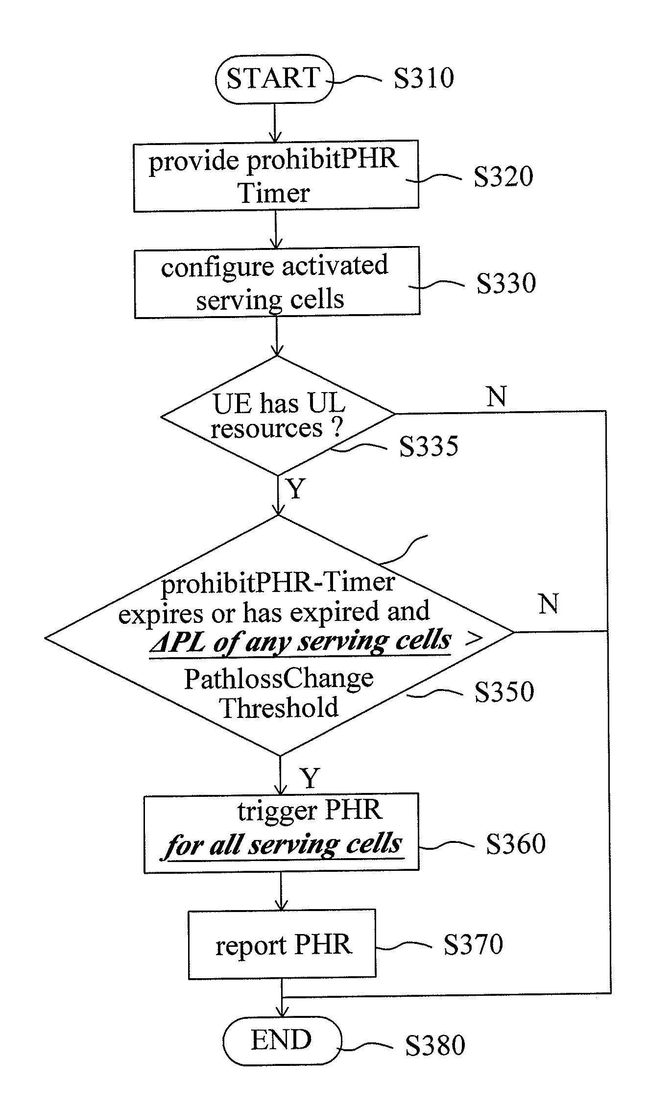
[0062]In uplink transmission, a UE transmits a Power Headroom Report (PHR) to an E-UTRAN NodeB (eNB) in order to assist with uplink scheduling. The eNB uses the information of the PHR when it determines the amount of resources, proper modulation and coding scheme (MCS) level for physical uplink shared channel (PUSCH) transmissions. In the embodiment, the UE is operated in a multi-carrier system and performs transmission / reception in a plurality of activated serving cells. Thus, the eNB needs the information of the PHR of each activated serving cell. Besides, it is assumed that the UE is operated in 3GPP LTE-Advanced system.

[0063]Please refer to FIG. 3 which illustrates a flowchart of a method for performing Power Headroom reporting procedure according to an embodiment of the present invention. A method for performing Power Headroom reporting procedure comprises following steps.

[0064]In step S310, the method for performing a Power Headroom reporting procedure star...

second embodiment

The Second Embodiment

[0073]In the embodiment, the UE is similarly operated in a multi-carrier system and performs transmission / reception in a plurality of activated serving cells. Besides, it is assumed that the UE is operated in 3GPP LTE-Advanced system. For conveniently describing the second embodiment, the method of performing Power Headroom reporting procedure is divided into a triggering PHR process and a reporting PHR process respectively illustrated in FIG. 4 and FIG. 6. Please refer to FIG. 4 which illustrates a flowchart of the triggering PHR process according to an embodiment of the present invention in advance. The triggering PHR process comprises following steps.

[0074]In step S410, the process for triggering the PHR starts.

[0075]In step S420, it is determined whether a prohibitPHR-Timer expires or has expired and at least one of the downlink path loss values is changed (ΔPL) more than a PathlossChange threshold since the last transmission of the previous PHR when the UE ...

third embodiment

The Third Embodiment

[0109]The abovementioned embodiments for triggering and reporting PHR is provided. In the present embodiment, a possible reporting form of PHR MAC control element is provided.

[0110]An implementation for the PHR MAC control element is provided in the embodiment. Please refer to FIG. 8 which illustrates an implementation of a PHR MAC control element according to an embodiment of the present invention. The implementation of a PHR MAC control element 800 comprises a Ci field 810 and a plurality of power headroom fields 820˜840.

[0111]The Ci field 810 is a bitmap which comprises a plurality of bits, and indicates whether each power headroom field 820˜840 of the corresponding serving cell is reported or not. For example, one bit of the Ci field 810 is set to “1” indicating that the power headroom field of the corresponding serving cell is reported; otherwise, one bit of the Ci field 810 is set to “0” indicating that the power headroom field of the corresponding serving ...


PUM


Abstract

This invention relates to a method for performing Power Headroom reporting procedure, adapted for a user equipment, wherein the user equipment is operated in a plurality of activated serving cells, the method includes the steps of: providing a prohibitPHR-Timer; obtaining a plurality of downlink path loss values respectively corresponding to the activated serving cells; triggering a power headroom report when the prohibitPHR-Timer expires or has expired and at least one of the downlink path loss values has changed more than a PathlossChange threshold since the last transmission of a PHR; and reporting the power headroom report.

Description

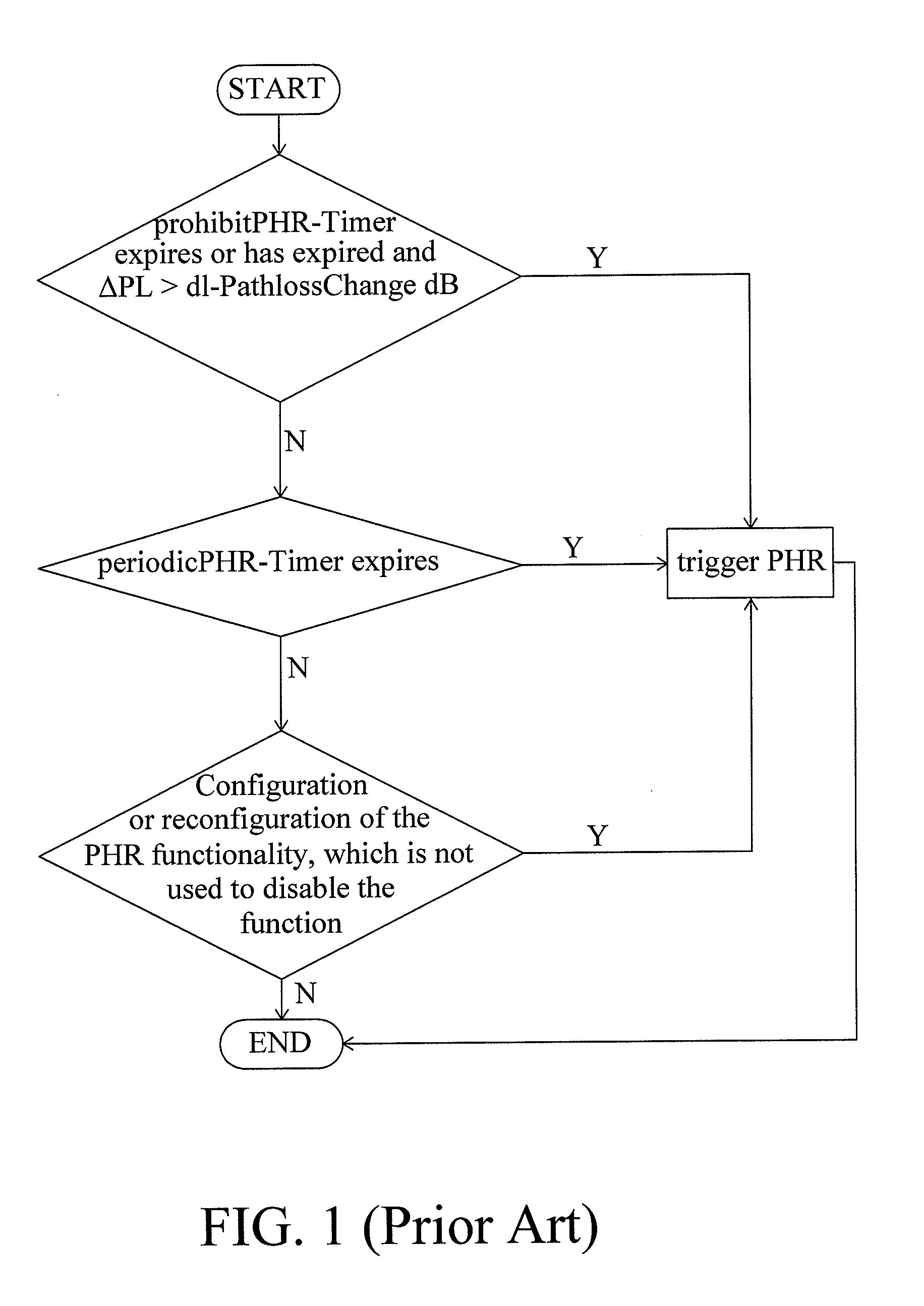
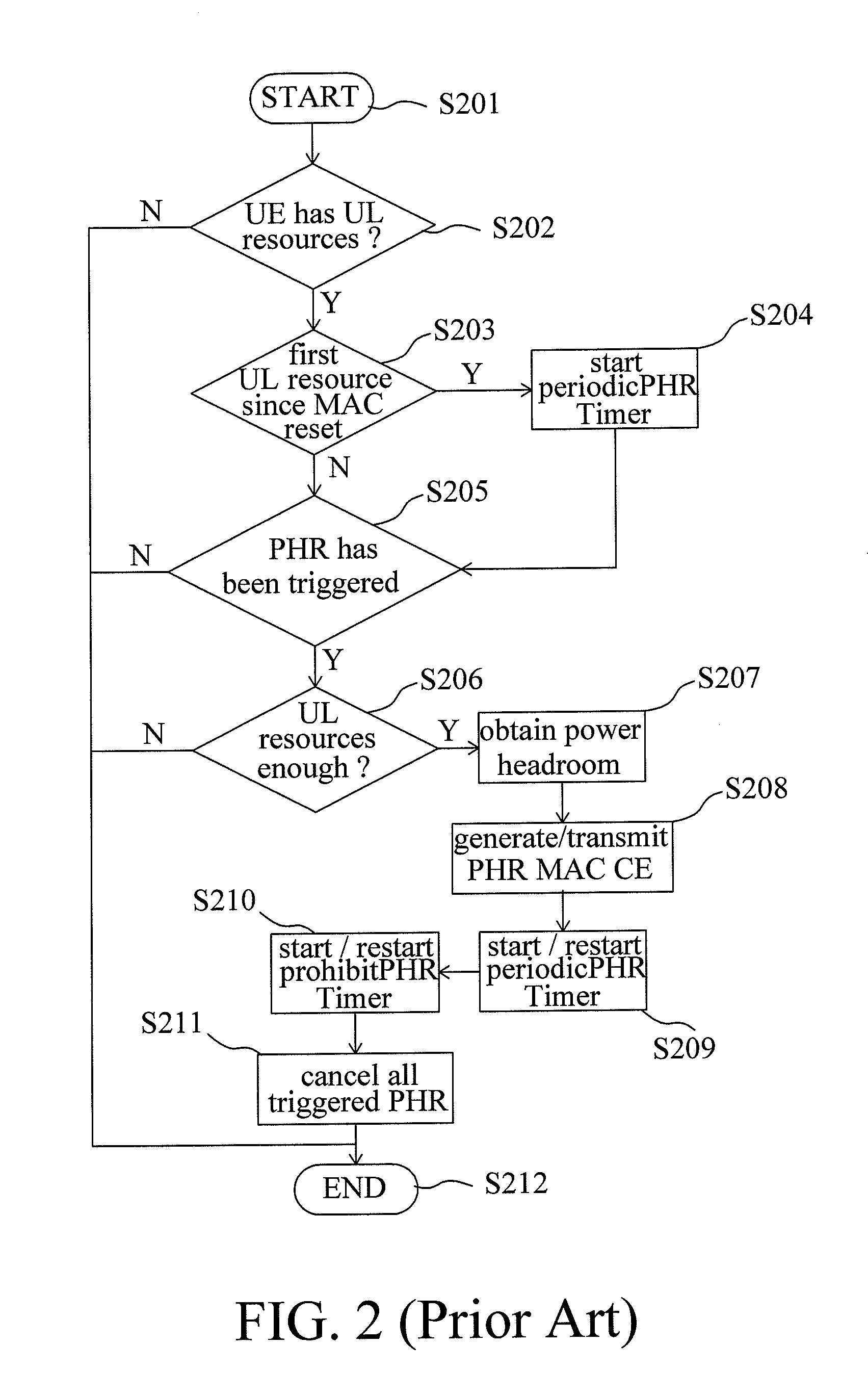
[0001]This application claims the benefit of U.S. Provisional Application No. 61 / 282813 filed on Apr. 6, 2010, U.S. Provisional Application No. 61 / 344237 filed on Jun. 17, 2010 and U.S. Provisional Application No. 61 / 410655 filed on Nov. 5, 2010, the content of which is hereby incorporated by reference.BACKGROUND OF THE INVENTION[0002]1. Field of Invention[0003]The present invention relates in general to a Power Headroom reporting mechanism, and more particularly to a Power Headroom reporting mechanism for radio resources allocation in a wireless communication system.[0004]2. Related Art[0005]In a wireless communication system, how to efficiently distribute / allocate uplink transmission resources between multiple user equipments (UEs) is always a critical issue from the system point of view. In order to achieve better radio resource management, some mechanisms which is used for enabling UEs to provide related information and informing the network side of some UE-specific power status...

Claims


Application Information

Patent Timeline
IPC IPC(8): H04L12/26H04W72/04
CPCH04W52/242H04W52/365H04W52/04H04W72/04H04W52/40
Inventor ZHANG, YUANYUANLU, TSUNG-LIANG
Owner HFI INNOVATION INC
Learn More