Synchronous transfer of streaming data in a distributed antenna system

a distributed antenna system and streaming data technology, applied in the field of wireless communication systems, can solve the problems of increasing the cost of the distributed antenna system, restricting the speed/phase control of synchronisation signals, and inability to receive such signals,

Active Publication Date: 2011-10-06
COMMSCOPE TECH LLC
View PDF7 Cites 105 Cited by
  • Summary
  • Abstract
  • Description
  • Claims
  • Application Information

AI Technical Summary

Problems solved by technology

Also, such techniques can be used to extend coverage to areas where RF propagation is limited by obstructions, such as buildings and tunnels, and to areas where the amount of traffic and revenue do not justify the investment for another base station.
Some standards, such as GSM impose such strict standards that they can only be met by frequency locking all signals used for frequency translation within the distributed antenna system to a single common standard.
However, this would significantly increase the cost of the distributed antenna system and in many applications where a distributed antenna system would be employed, such as in buildings or tunnels, reception of such signals is problematic at best and nonexistent at worst.
But adding extra cables multiplies the cost of deployment and in some cases may not be physically possible.
Moreover, adding additional wires to cables is not always possible as is the case in applications using existing CAT 5 / 6 / 6A cable in buildings or other structures, where all cable pairs are required for high speed data transfer and / or are already otherwise used.
Use of unshielded twisted pair cables, however, results in additional susceptibility to interfering signals.
High data rate serial protocols, such as 10 GBase-T Ethernet, which are required to handle the high data rates necessary to transport wideband digitized RF, are particularly susceptible to alien crosstalk because of the more complex modulation schemes and wide bandwidths employed by such formats.
Increased crosstalk and noise will lead to more jitter on the data and, hence, more jitter on the recovered clock as well.
But such fiber optic cables and shielded cables, as well as the equipment used therewith, is often cost prohibitive and also cannot be used in those applications attempting to reuse cable already in buildings.

Method used


Image

  • Synchronous transfer of streaming data in a distributed antenna system
  • Synchronous transfer of streaming data in a distributed antenna system
  • Synchronous transfer of streaming data in a distributed antenna system

Examples


Embodiment Construction

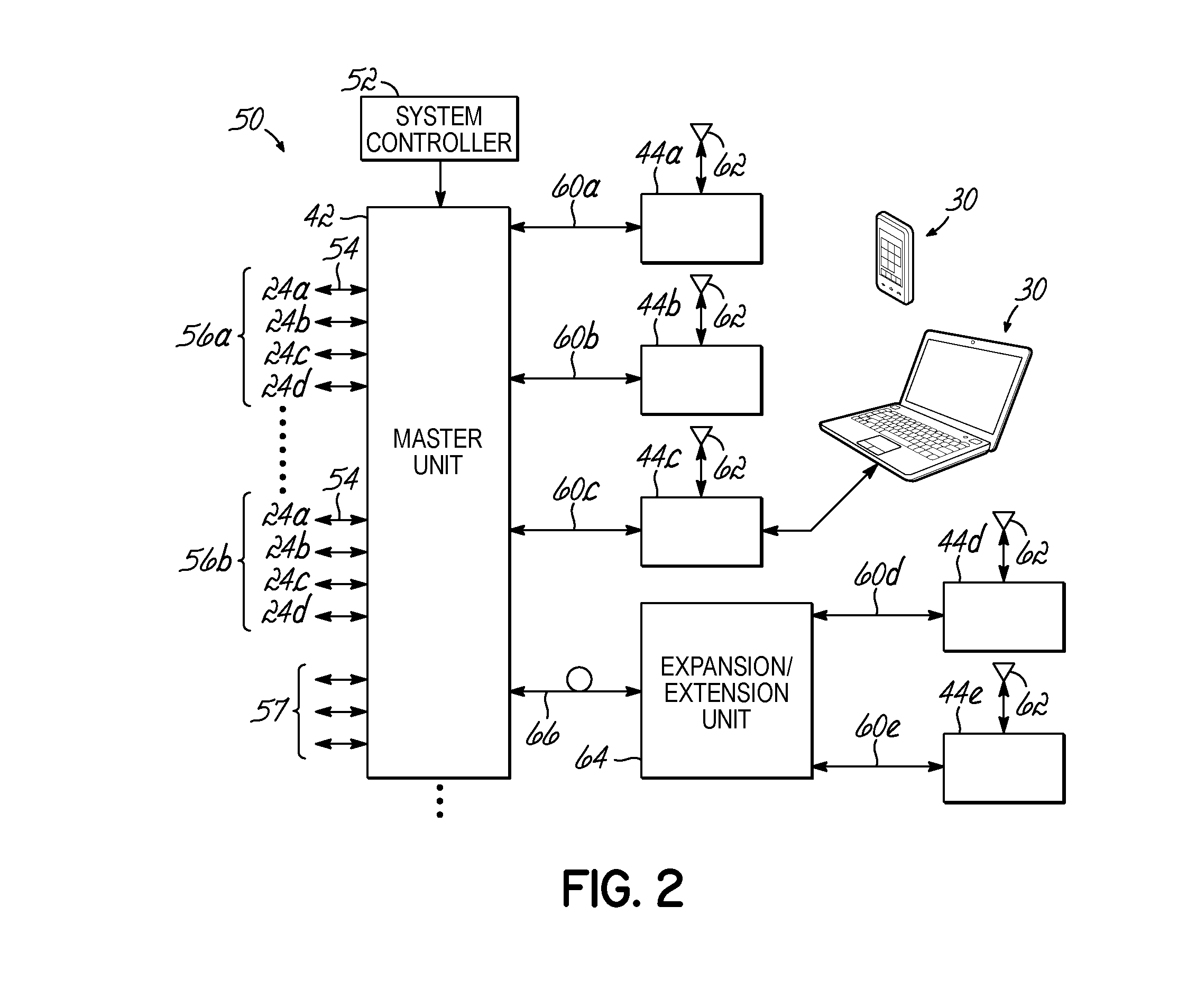
[0023]Embodiments of the present invention provide a remote unit that can be used to recover a clock signal embedded in a modulated signal. To do this, embodiments of the invention are capable of extracting the clock signal from the modulated signal, reducing the jitter on that extracted signal, then scaling the frequency of that signal. Advantageously, this allows a master unit to communicate with remote units over an unshielded twisted pair cable such that the cost for deployment is lessened. Embodiments of the invention further account for distributed antenna systems that use a mixed combination of fiber optic and twisted pair cables and also can be used to recover a clock signal embedded as a component of the modulated signal.

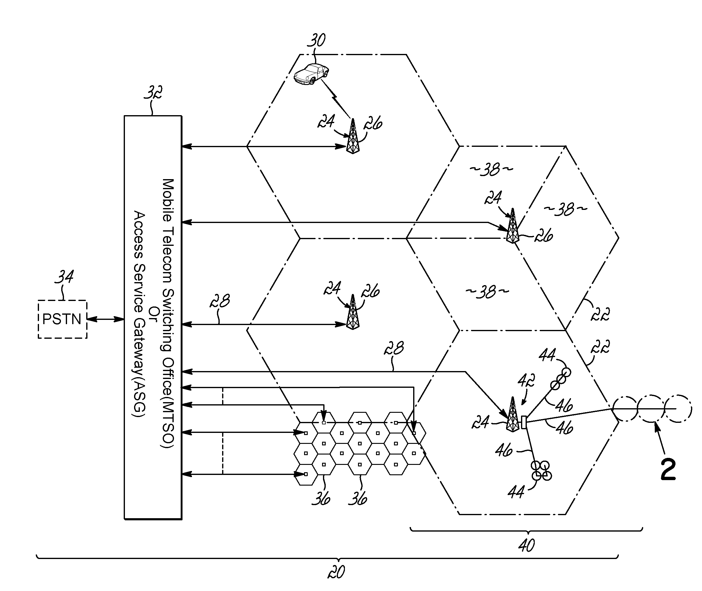
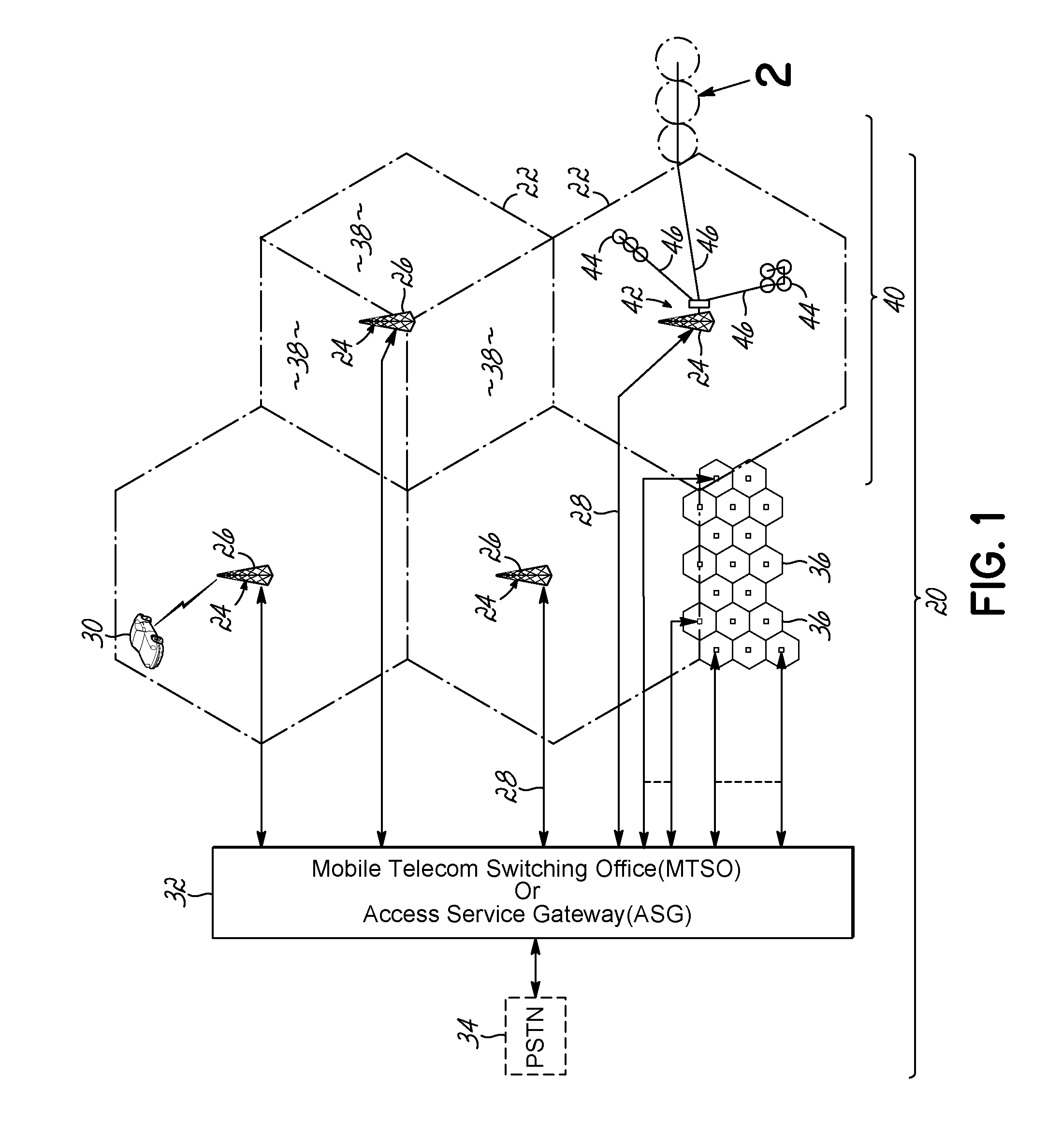
[0024]Cellular phone systems and broadband wireless metropolitan networks 20, as shown in FIGS. 1 and 2, are generally divided into a number of cells 22 distributed in a pattern to preclude co-channel interferences and provide coverage of mobile and fixed s...


PUM


Abstract

Embodiments of the invention provide a method, distributed antenna system, and components that generate a jitter reduced clock signal from a serial encoded binary data stream transmitted over a communication medium. The method comprises receiving a modulated signal that includes the encoded binary data stream and extracting the encoded binary data stream. The method further comprises generating a recovered clock signal that is phase locked to the encoded binary data stream, generating an error signal based on a difference between a phase of the encoded binary data stream and the recovered clock signal, and integrating the error signal to generate a signal to control a voltage controlled oscillator. The method further comprises generating a stable recovered clock signal and producing at least one output clock by scaling the stable recovered clock signal frequency.

Description

CROSS-REFERENCE TO RELATED APPLICATION[0001]This Application claims the benefit of U.S. Patent Application Ser. No. 61 / 319,623 to McAllister et al. entitled “SYNCHRONOUS TRANSFER OF STREAMING DATA VIA ETHERNET PHYS AND MECHANISMS OF CLOCK RECOVERY AND SYNCHRONIZATION” and filed on Mar. 31, 2010, which application is incorporated by reference in its entirety herein.FIELD OF THE INVENTION[0002]The present invention is directed to wireless communication systems, and specifically is directed to the synchronous transfer of streaming data in a distributed antenna system.BACKGROUND OF THE INVENTION[0003]Conventional communication systems, such as cellular phone systems and broadband wireless metropolitan networks, are often divided into a number of cells. These cells are typically distributed in a pattern to preclude co-channel interference and thus provide coverage of subscriber units operating within the service area of the system. In some systems, each cell includes a base station that ...

Claims


Application Information

Patent Timeline
Patent Type & Authority Applications(United States)
IPC IPC(8): H03D3/24
CPCH04J3/0658H04L7/033H04L7/0087H04L1/0631H04W88/085H04L7/00H04L7/02H04L7/04H04L1/0625
Inventor MCALLISTER, DONALDRANSON, CHRISPHILLIPS, FRED WILLIAM
Owner COMMSCOPE TECH LLC
Why Eureka
Try Eureka