Fundus image display apparatus, control method thereof and computer program
- Summary
- Abstract
- Description
- Claims
- Application Information
AI Technical Summary
Benefits of technology
Problems solved by technology
Method used
Image
Examples
first embodiment
Visualization of a Blood Vessel
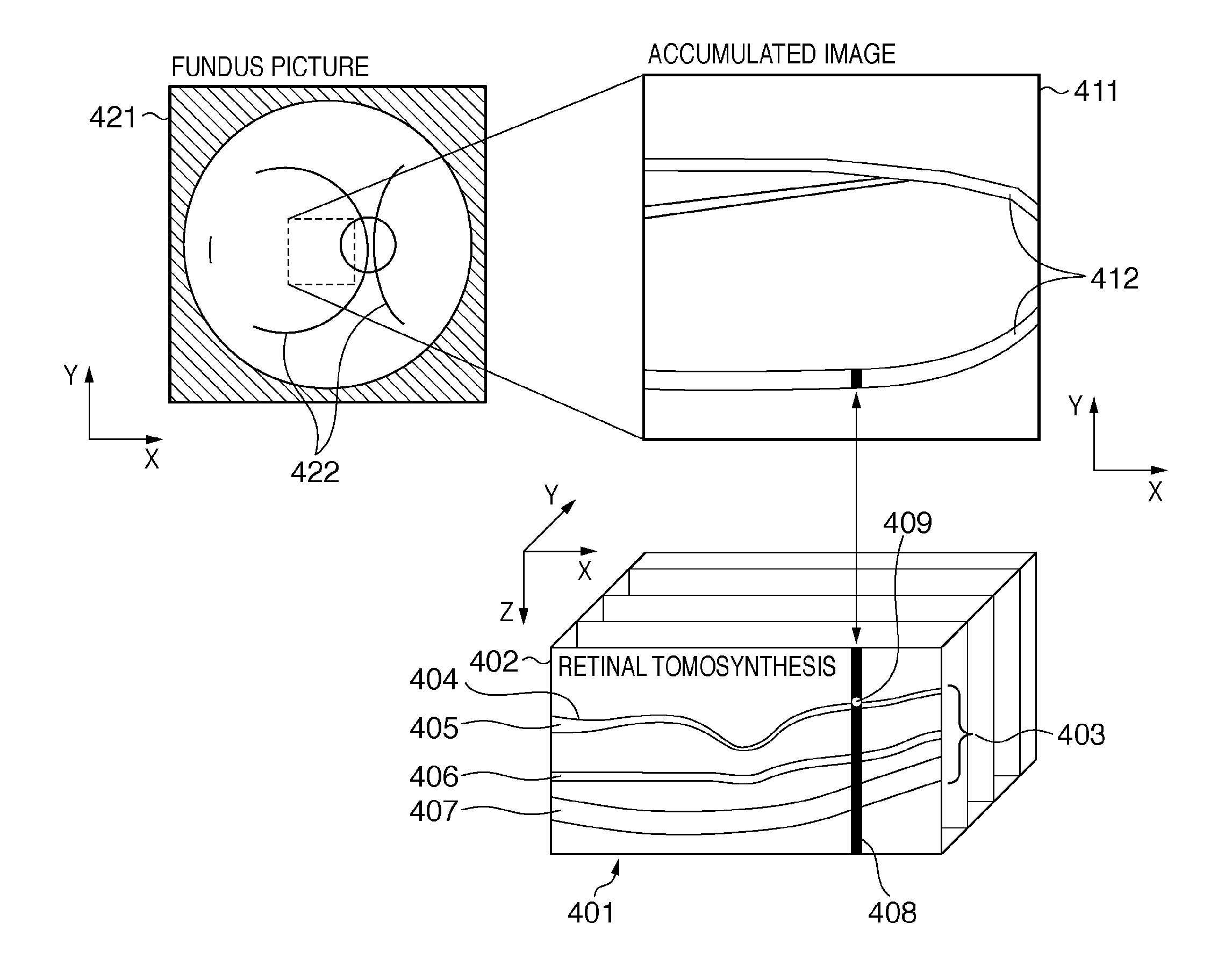
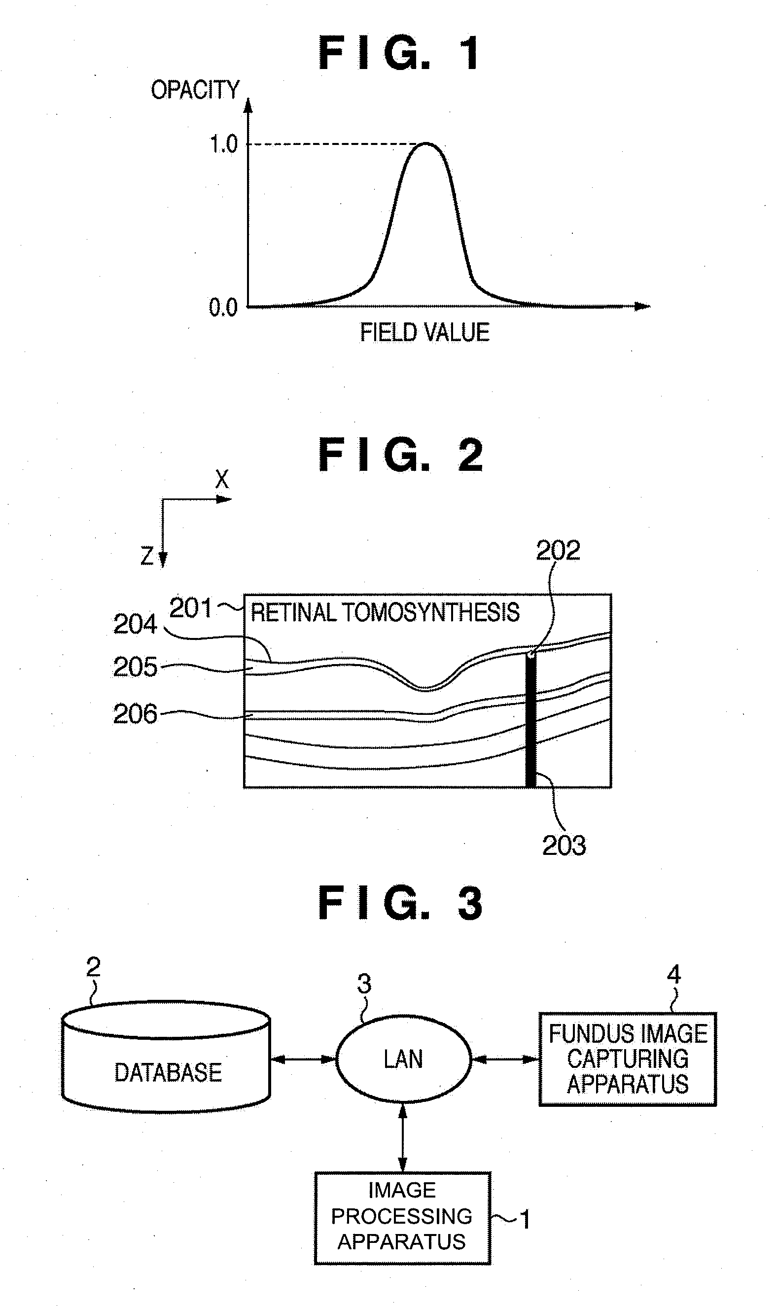
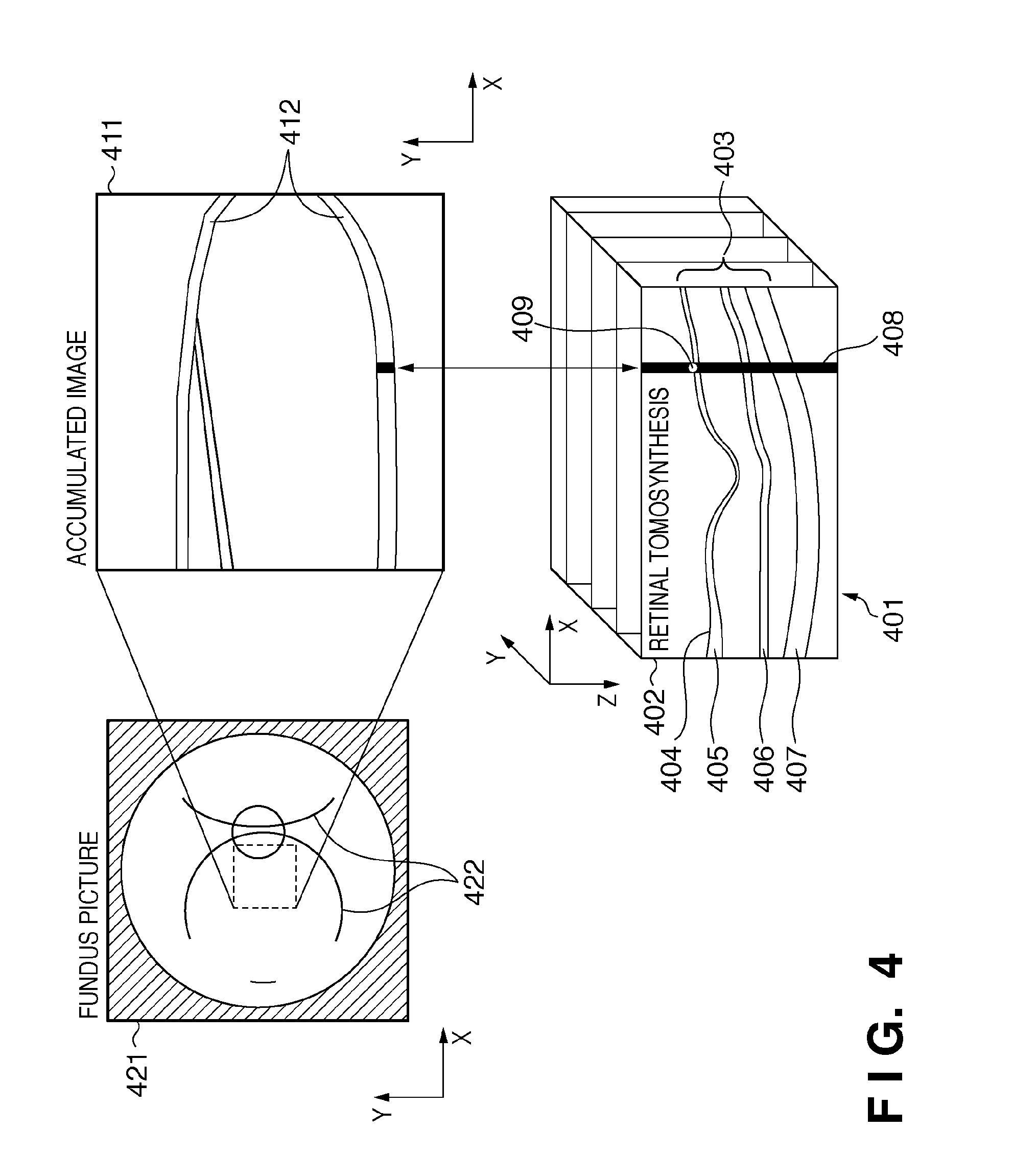
[0025]FIG. 3 is a chart showing one example of the structure of a fundus image display apparatus according to the present embodiment. In this embodiment, a fundus image display apparatus 1 reads out a fundus image from a database 2 through a LAN 3. Alternatively, a memory device such as an FDD, CD-RW drive, MO drive, or ZIP drive, or the like. may be connected to the fundus image display apparatus 1 and the fundus image may be read out from such a drive. In addition, a medical image or the like may be obtained directly from a fundus image capturing apparatus 4 via the LAN 3. In addition to the fundus image, the database 2 stores patient names or patient data, thickness information of a retina 403, nerve fiber layer 405, outer plexiform layer 406, and the retinal pigment epithelium 407 shown in FIG. 4. FIG. 4 is a chart for explaining the relationship between the fundus picture, retinal volume data and the accumulated image.
[0026]As the fundus image cap...
second embodiment
Visualizing the Achromoderma
[0051]In the above first embodiment, the three-dimensional running of the fundus blood vessel is visualized by extracting the blood vessel area and the layer boundary from the fundus image, and by volume-rendering the blood vessel using the opacity calculated from the distance from the layer boundary and the luminance value of the retinal volume data. On the other hand, in the second embodiment, not the blood vessel but the achromoderma is visualized as the discriminative lesion of the fundus oculi.
[0052]The structure of the fundus image display apparatus and the apparatus connected thereto is same as that of the first embodiment as shown in FIG. 2. However, the functional block of the fundus image display apparatus according to the present embodiment is configured by adding an achromoderema area extraction unit 1001 to the functional block according to the first embodiment as shown in FIG. 10.
[0053]In the description hereinafter, the achromoderma area ex...
third embodiment
[0062]The fundus image display apparatus and the apparatus connected thereto are same as those of the first embodiment, as shown in FIG. 2. The basic structure of the computer for realizing the function of the respective units is also same as that of the first embodiment, as shown in FIG. 12.
[0063]The distance transfer function setting unit 505 in the first and second embodiments comprises an average thickness of the retina obtaining unit 701, function parameter input unit 702, a shadow area extraction unit 703, the achromoderma center searching unit 704 and a layer boundary obtaining unit 705, as shown in FIG. 7. The distance transfer function is set by using the shadowed area extraction unit 703 in the first embodiment and by using the achromoderma center searching unit 704 in the second embodiment. In the present embodiment, the method of setting the distance transfer function by using one of the average thickness of the retina obtaining unit 701, the function parameter input uni...
PUM
 Abstract
Description
Claims
Application Information
 - R&D
- Intellectual Property
- Life Sciences
- Materials
- Tech Scout
- Unparalleled Data Quality
- Higher Quality Content
- 60% Fewer Hallucinations
Browse by: Latest US Patents, China's latest patents, Technical Efficacy Thesaurus, Application Domain, Technology Topic, Popular Technical Reports.
© 2025 PatSnap. All rights reserved.Legal|Privacy policy|Modern Slavery Act Transparency Statement|Sitemap|About US| Contact US: help@patsnap.com


