Gas burner

a burner and gas technology, applied in the field of gas burners, can solve the problems of insufficient surface treatment applications on a very high quality level, and high machine and/or labor costs, and achieve the effects of less demanding production, high heat and oxidation resistance, and easy and thorough cleaning of the nozzles

Inactive Publication Date: 2011-10-06
TETRA LAVAL HLDG & FINANCE SA
View PDF5 Cites 15 Cited by
  • Summary
  • Abstract
  • Description
  • Claims
  • Application Information

AI Technical Summary

Benefits of technology

[0019]Flame arrays produced by burners according to the invention are able to satisfy the highest standards regarding flame treatment quality and are considerably less demanding regarding production than the known one-piece bronze nozzle plates. A further advantage of the burner according to the invention is the simplicity of production of nozzle plates or adaptation of one nozzle plate for differing requirements (differing treatments, differing gases etc.), wherein from only a small number of different sheet types, it is possible to produce a large number of different nozzle plates by stacking different numbers of sheets and/or

Problems solved by technology

However, the nozzle cross sections and the nozzle lengths vary substantially randomly within a range of cross sections and lengths, which proves to be non-sufficient for surface treatment applications on a very high quality level.
However, such a nozzle plate needs a high density of small

Method used


Image

  • Gas burner
  • Gas burner
  • Gas burner

Examples


Embodiment Construction

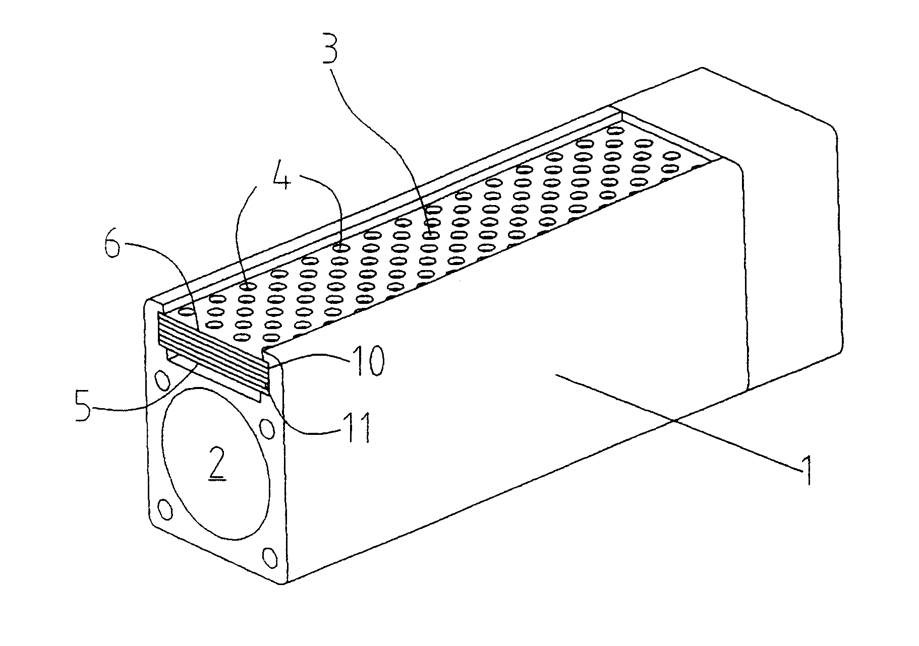
[0026]FIG. 1 shows a first exemplary embodiment of the gas burner according to the invention, which gas burner comprises a burner body 1 with a gas supply connection 2 and a nozzle plate 3, wherein the burner body 1 and the nozzle plate 3 constitute together a gas plenum and the nozzle plate 3 constitutes a perforated wall section of the plenum. The nozzles 4 of the nozzle plate 3 reach from a plenum side 5 to a flame side 6 of the nozzle plate 3. For ease of illustration, the relations between dimensions of the burner according to FIG. 1 do not coincide with the relations of a real burner. In particular, the burner body will usually be longer and the nozzles will be smaller and nearer together than illustrated.

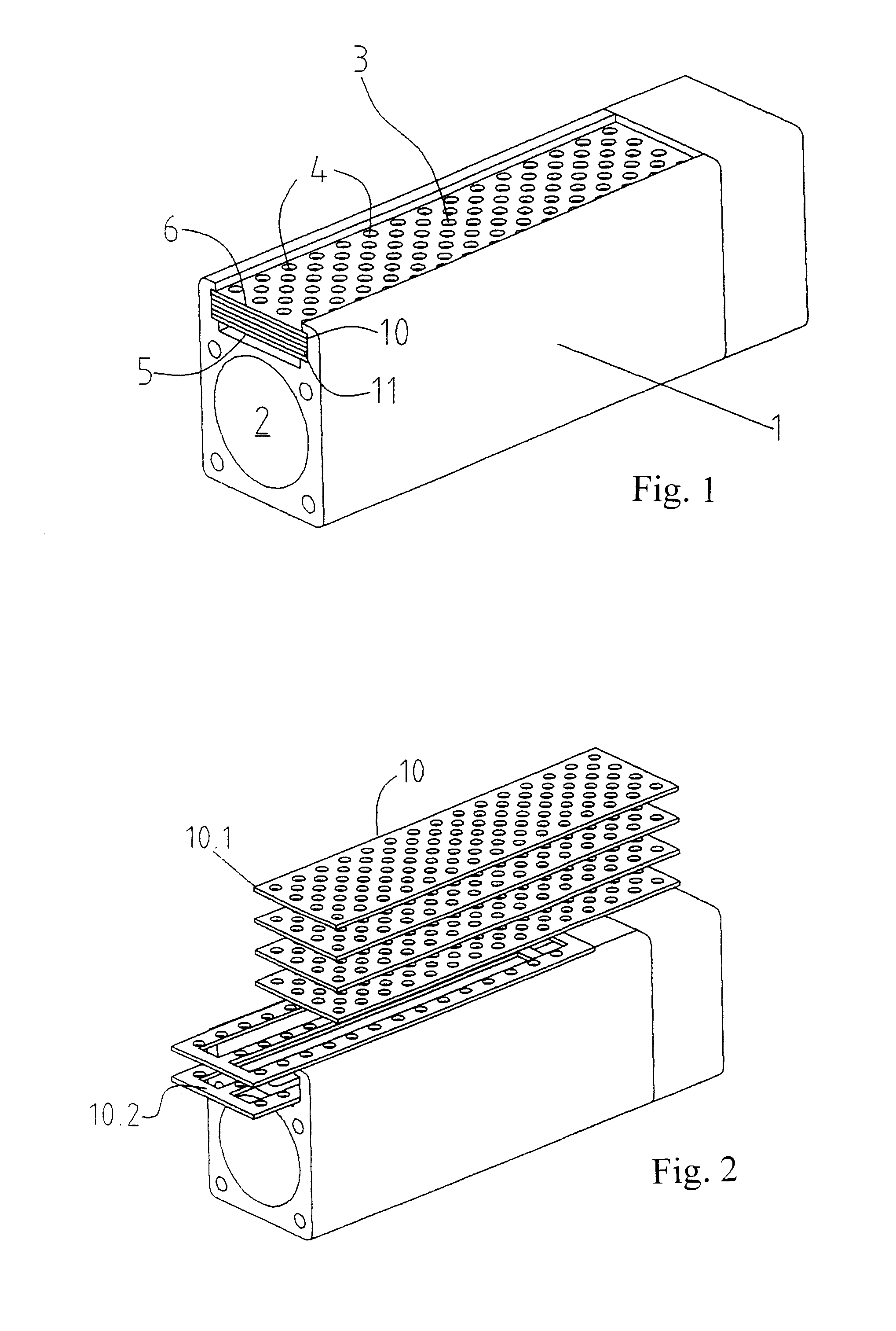
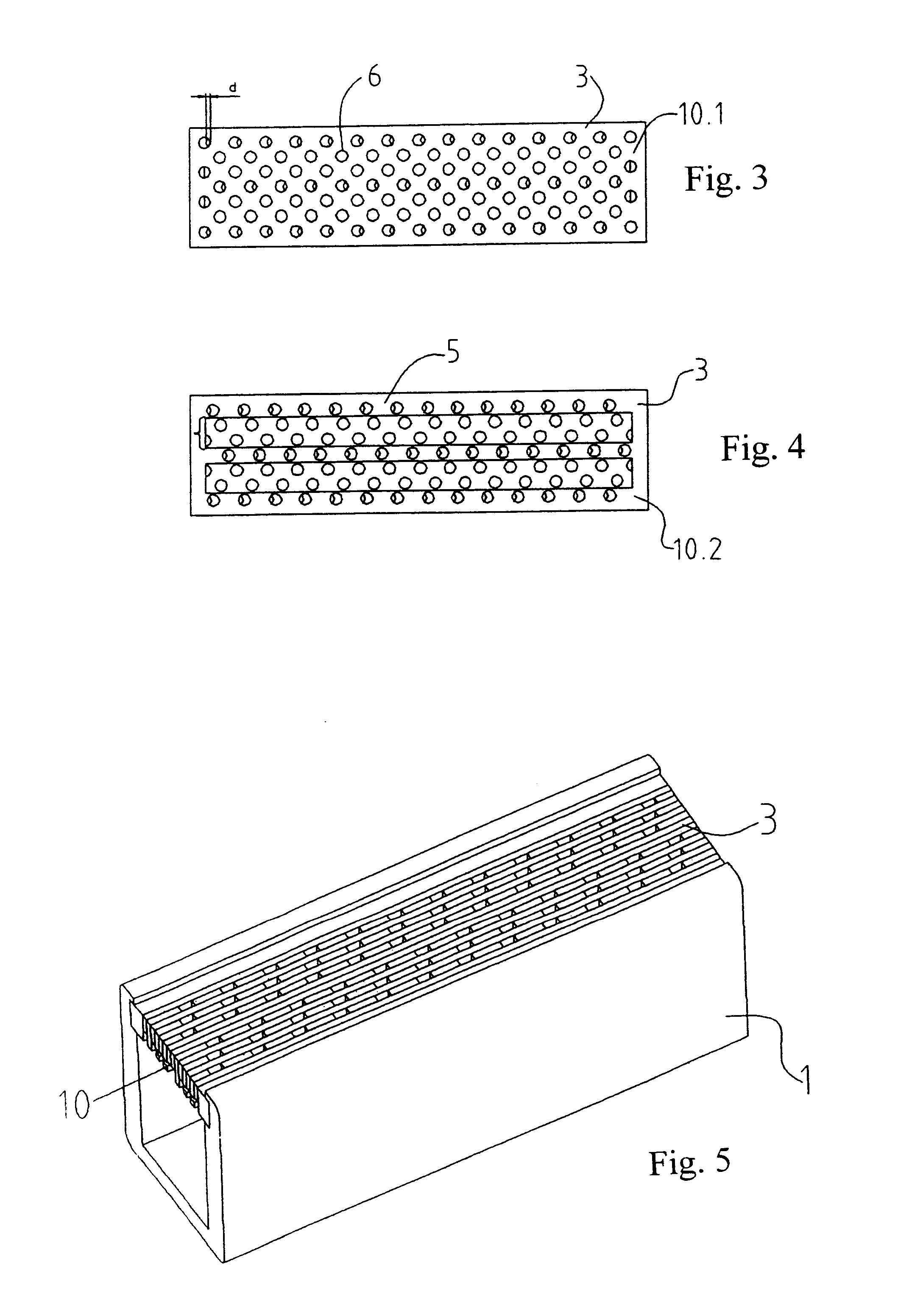
[0027]The nozzle plate 3 comprises a plurality of sheets 10 (e.g. six sheets, as illustrated in FIG. 1) which extend substantially perpendicular to the length of the nozzles, comprise determinate through openings and are stacked such that the through openings of each sheet ar...


PUM

PropertyMeasurementUnit
Timeaaaaaaaaaa
Thicknessaaaaaaaaaa
Thicknessaaaaaaaaaa

Abstract

A gas burner, which is particularly suitable for flame treatment of substrates having large surfaces, e.g. for coating such surfaces in a combustion chemical vapor deposition (CCVD) process, includes a burner body with a gas supply connection and a nozzle plate, wherein the burner body and the nozzle plate constitute together a gas plenum and the nozzle plate constitutes a perforated wall section of the plenum. The nozzle plate includes a large number of nozzles extending from a plenum side to a flame side of the nozzle plate and it is made of a plurality of sheets which are arranged in a stack and extend substantially perpendicular or substantially parallel to the nozzle extension. The sheets include through openings, wherein the through openings of all sheets are at least partly aligned with each other, or they have a comb-like form.

Description

BACKGROUND OF THE INVENTION[0001]1. Field of the Invention[0002]The invention concerns a gas burner according to the generic part of the independent claim. The gas burner is suitable for establishing an array of flames with characteristics such that it is applicable e.g. in a device for flame treatment of substrate surfaces, in particular for flame treatment of large substrate surfaces, e.g. in order to activate the surfaces or in order to coat the surfaces in a so called combustion chemical vapor deposition (CCVD) process.[0003]2. Description of Related Art[0004]Installations for flame treatment of substrates having large surfaces, e.g. of quasi endless webs of polymer film, paper board, metal foil, extruded melt curtains or combinations thereof are usually equipped with a gas burner or a plurality of gas burners and with means (e.g. rotating drum) for moving the substrate through or past the flame array produced by the gas burner(s). The flame arrays usually have the form of flame...

Claims


Application Information

Patent Timeline
IPC IPC(8): F23D14/62F23D99/00
CPCF23D14/10F23D99/003F23D14/586C23C16/453F23D91/02
Inventor ROCHAT, GILFAYET, PIERRERICHTER, THOMASZOBEL, BERNHARD
Owner TETRA LAVAL HLDG & FINANCE SA
Why Eureka
Try Eureka