Test equipment for verification of crystal linearity at high-flux levels

a technology of crystal linearity and test equipment, applied in the field of xray detector crystals, can solve the problems of leakage current and noise in the detector network, and achieve the effect of optimizing life and reliability and efficient operation

Active Publication Date: 2011-10-13
SURESCAN CORP
View PDF2 Cites 11 Cited by
  • Summary
  • Abstract
  • Description
  • Claims
  • Application Information

AI Technical Summary

Benefits of technology

[0019]In addition to the thermal control network for the crystals, the electronic devices associated with each detector crystal are independently cooled using a second set of Peltier devices so that lifetime and reliability are maximized. These Peltier devices pump heat from the electronics into the outer housing. In most operating environments the ambient temperature is less than the operating temperature of the detector crystals, so heat removed from the electronics can be used to heat the detector crystals, resulting in efficient operation.

Problems solved by technology

Leakage current, which creates noise in the detector network, is not critically important in this application because spectral integration reduces its impact.

Method used


Image

  • Test equipment for verification of crystal linearity at high-flux levels
  • Test equipment for verification of crystal linearity at high-flux levels
  • Test equipment for verification of crystal linearity at high-flux levels

Examples


Embodiment Construction

[0027]The present invention is described with reference to the accompanying FIGS. 1 through 5, where like reference numbers correspond to like elements.

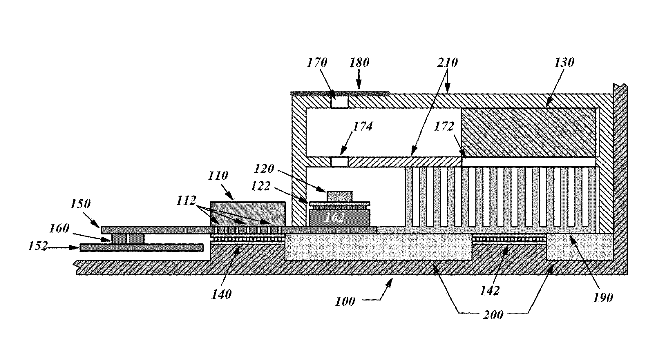
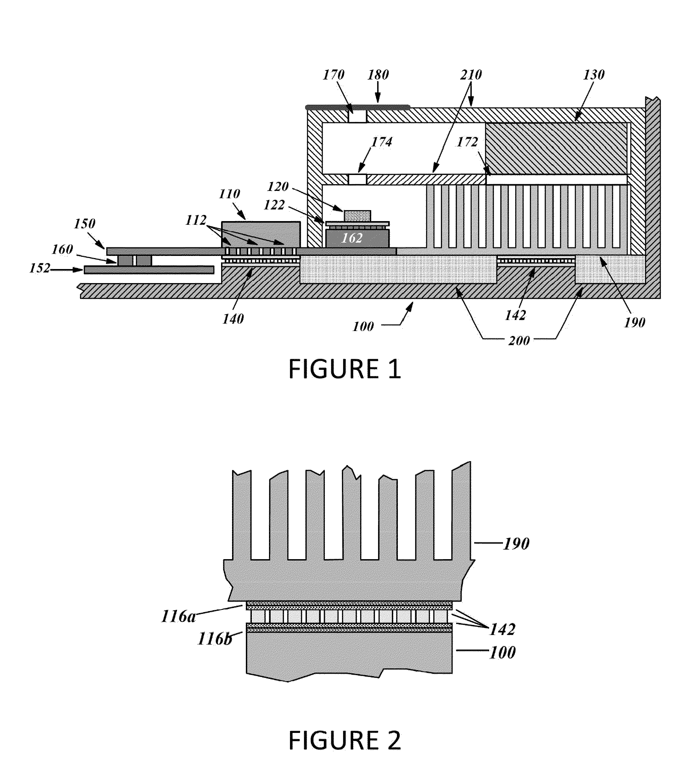
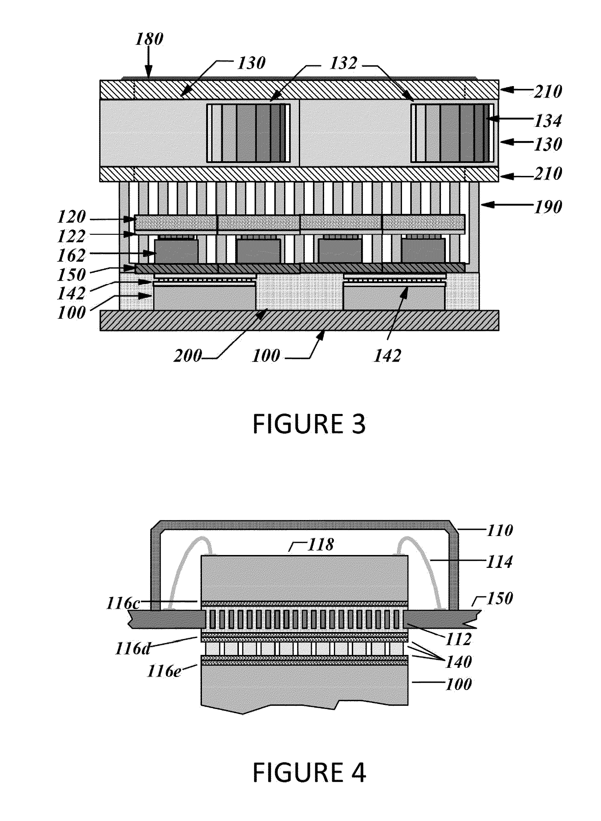
[0028]FIGS. 1 through 4 are partial drawings of an x-ray detector assembly. In FIGS. 1 and 3, only a portion of the outer enclosure 210 is shown for clarity. It is understood that additional electronics, well known to those versed in the art, have been omitted from the drawings for clarity.

[0029]FIG. 1 is a cross-sectional view of the invention. Air-flow is substantially two-dimensional and in the cutting plane used to produce this view. The temperature of the package housing the photon counting electronics 110 is cooled while the detector crystals 120 are maintained within a narrow range of temperatures. In one embodiment the temperature of crystals 120 is controlled to within ±2° C. However, tighter control, to within ±0.5° C., is desirable.

[0030]The detector crystals 120 are isolated within insulating enclosure 210. In a preferred...


PUM


Abstract

A method and device that provides independent temperature control of x-ray detector crystals, either singly or in small groups. In addition to a thermal control network for the crystals, electronic devices are associated with each detector crystal and are independently cooled using Peltier devices so that lifetime and reliability are maximized. In most operating environments the ambient temperature is less than the operating temperature of the detector crystals. In these situations, the heat removed from the electronics can be used to heat the detector crystals, resulting in efficient operation.

Description

FIELD OF THE INVENTION[0001]The present invention relates to x-ray detector crystals and, more particularly, to a method and device that provides independent temperature control of x-ray detector crystals, either singly or in small groups.BACKGROUND OF THE INVENTION[0002]It is well-known that temperature has a significant effect on the performance of pixilated semiconductor and semi-insulator materials used for photon counting in CT machines. In particular, CdTe, CdTe:Cl, CdZnTe, HgI2, and other semi-insulators exhibit poor carrier transport properties so that significant space charge can build within the material during use. This space charge affects the induced signal, resulting in tailing of the spectrum (i.e., spreading of the lower energy tail), spectral broadening, as characterized by FWHM measurements, and spectral shifts. The counter can become highly non-linear and, in extreme cases, even cease to function.[0003]At low flux, space charge has very little effect. In certain m...

Claims


Application Information

Patent Timeline
Patent Type & Authority Applications(United States)
IPC IPC(8): G01T1/24G01T7/00H05K7/20
CPCH01L23/3677H01L23/38H01L31/0203H01L31/085H01L2224/32225H01L2224/48227H01L2224/73265H01L2924/00
Inventor CROCKER, MICHAELHART, LIZAJOHNSON, ERICKIBALLA, GERALD
Owner SURESCAN CORP
Why Eureka
Try Eureka