
Perimeter security system using active analysis of images reflected by a set of mirrors onto a video camera

a security system and mirror technology, applied in the field of mirror security systems, can solve the problems of only being able to operate, providing very partial protection of the space between the emission and reception surface, and short range, so as to reduce the influence of sunlight and increase the contrast between the image area of the reflector and the rest of the imag

Inactive Publication Date: 2011-10-13
TAILLADE BERNARD
View PDF3 Cites 10 Cited by
  • Summary
  • Abstract
  • Description
  • Claims
  • Application Information

AI Technical Summary

Benefits of technology

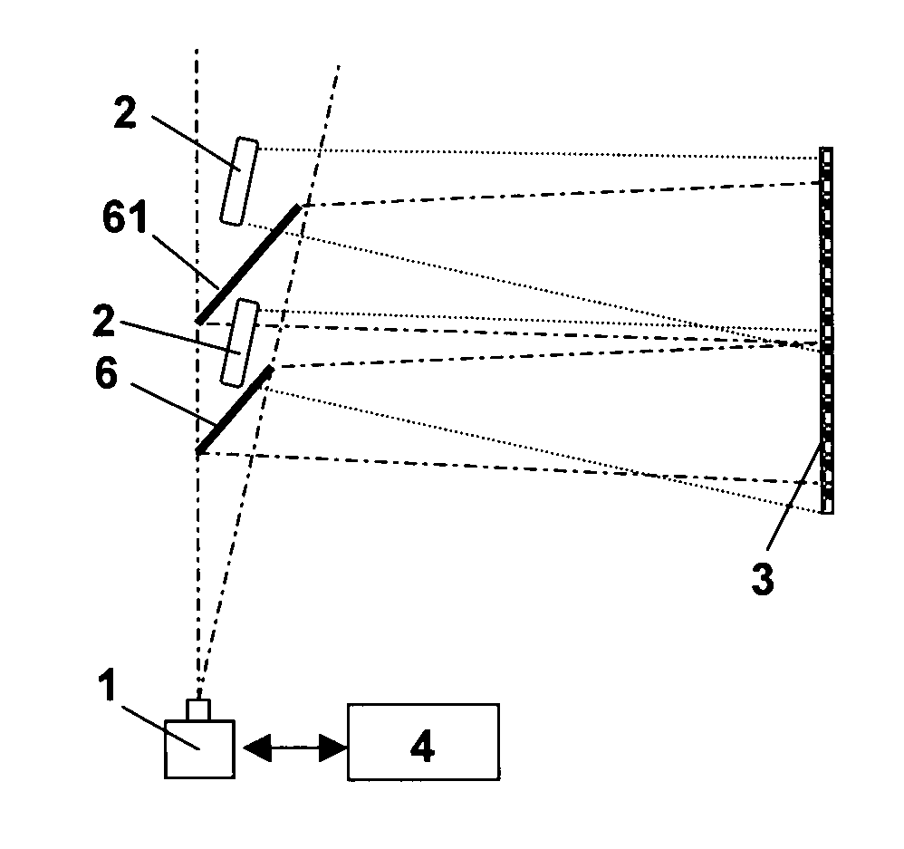
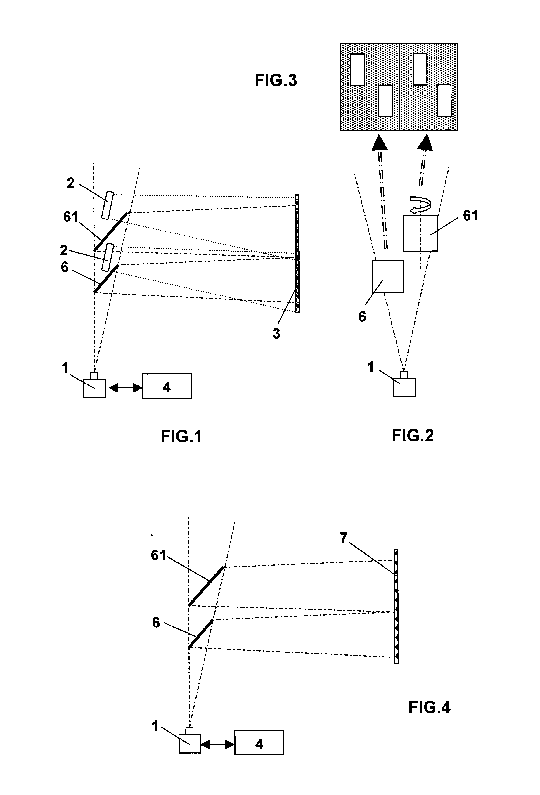
[0009]The problem this invention proposes to solve consists of replacing a set of cameras, whose signals must be synchronized in order to simultaneously detect and measure a rapid variation in the field of these cameras, by a set of mirrors for a lower cost price and requiring a much less sophisticated, since unique, image processing system.
[0015]In the case in which a retro-reflector type of reflector is used, the system controls the round-trip path of a controlled beam because it generates a quasi-saturated signal on a known, illuminated and controlled portion of the scene, namely the scene portion sent back by the reflector whose direction of light reflection is known and controlled. It allows very precise analysis of the surface of the image area of the reflector, the level of which is controlled (quasi-saturation) and the total or partial screening of which by an object generates a negative variation of the signal over a portion of the image sensor. The reflector can be large so that the sensitive area of detection is equally large. Once the breach has been definitively detected, the device can behave as a conventional video detection and visualization system to monitor changes in the breach within the camera's field of view. According to particular embodiments of the invention, the unit for analyzing and processing images and controlling the camera is designed to:
[0016]control the latter's electronic shutter so as to vary the sensors exposure time, and thus the value of the signal provided by said camera;
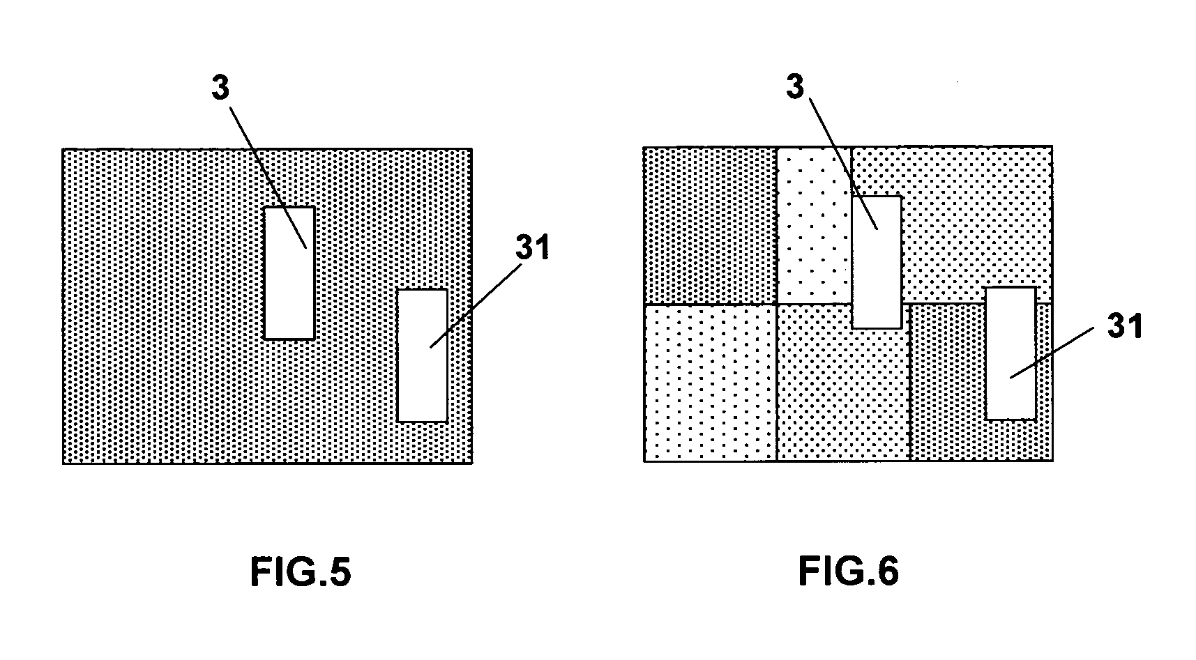
[0020]each camera or each reflector, or both, may be equipped with a band-pass filter whose transmitting wavelength is centered on the corresponding projectors wavelength so that each camera mostly perceives light beams from the corresponding projector and perceives little or none of the other beams having a different wavelength, this is in order to decrease the influence of sunlight or any other lighting device not forming part of the device: this selective filtering on the beams' wavelength allows the contrast between the reflectors image area and the rest of the image to be increased.

Problems solved by technology

Moreover, this type of device requires wiring on both sides of the sensitive area and only provides very partial protection of the space between the emission and reception surfaces, in other words being limited to the surface of the receivers' lenses.
They generally have a very short range and their operation is only possible when the area of reflection, and therefore of detection, is a limited, single surface.
In this case this results in it being impossible to detect definitively a partial but real cutoff of the beam.
There are however a large number of problems posed by this type of device, the first being that the system in question is passive and if an obstacle has been introduced into the scene while the system is stopped, then the fact that the sensitive area is breached behind the obstacle with respect to the camera becomes undetectable by the system.
In addition, variations of light and movements of shadows make this equipment very sensitive to climatic conditions, and variations in the video signal not solely due to the passage of an object in the sensitive area.

Method used


Image

  • Perimeter security system using active analysis of images reflected by a set of mirrors onto a video camera
  • Perimeter security system using active analysis of images reflected by a set of mirrors onto a video camera
  • Perimeter security system using active analysis of images reflected by a set of mirrors onto a video camera

Examples


Embodiment Construction

[0028]The system represented is of the type comprising:[0029]a video camera (1) whose sensitive sensor operates in both the visible and near-visible spectra;[0030]a means (3, 7) designed to transmit or re-transmit, in the visible but also in the near-visible spectrum, a beam illuminating the scene viewed by the camera;[0031]a unit (4) for analyzing and processing images and controlling the camera (1) designed to define one or more analysis frames of the image portion or portions containing the illumination means (3, 7) and to analyze this portion of the image in order to detect any rapid variation of the video signal in the image area of said illumination means corresponding to the passage of an object or a person between the assembly comprising the camera (1) and said means (3, 7); the size of the screened image area varies according to the distance to the breach and according to the height of the object or person making the breach in the area masking the illumination means (3, 7)....


PUM


Abstract

A perimeter security system includes a video camera (1), an element (7) for transmitting or retransmitting a radiation lighting a scene observed by the camera (1), and a unit (4) for image analysis and processing and for driving the camera (1). The system is essentially characterized in that it includes, in order to multiply the number of shots while using a single camera (1), at least two mirrors (6, 61) partially inserted into the field of vision of the latter, each mirror having the same vertical orientation but a different horizontal orientation so that the portion of the image seen by the camera on each of the mirrors always represents the same scene relative to the lighting element (7).

Description

FIELD OF THE INVENTION[0001]This invention relates to a perimeter security system using active analysis of images reflected by a set of mirrors onto a video camera.TECHNOLOGICAL BACKGROUND[0002]The most common perimeter security systems are based on detecting breach of a sensitive area by means of a device detecting one or more infrared beams being cut. They generally consist of pair(s) of transmitter(s) and receiver(s) operating through a coding and / or synchronization of pulsed infrared beams between the transmitters and receivers. According to a first embodiment of said systems, the transmitter and receiver are placed facing each other on either side of the sensitive area to be monitored, which is traversed by the infrared beam or beams. The total screening by an object of the path of a beam, which corresponds to that of the lens located in front of the receiver, triggers an alarm if the beam, and therefore the infrared signal, is cut for a period greater than a generally paramete...

Claims


Application Information

Patent Timeline
Patent Type & Authority Applications(United States)
IPC IPC(8): H04N7/18
CPCG01V8/14G08B13/1961G08B13/19641H04N7/188H04N5/2353H04N7/18H04N5/2351H04N23/71H04N23/73
Inventor TAILLADE, BERNARD
Owner TAILLADE BERNARD
Learn More