Optical instrument for testing optical systems and samples

Inactive Publication Date: 2011-10-13
VTT NTM OU
View PDF2 Cites 4 Cited by
  • Summary
  • Abstract
  • Description
  • Claims
  • Application Information

AI Technical Summary

Benefits of technology

[0020]4. The cross-like scheme is replaced with the parallel light beam tracks wh

Problems solved by technology

The prototype has the following disadvantages:1. Instability of work of the autocollimating illuminating system and difficulties of its adjustment; difficulties are rather considerable because of necessity to fulfil simultaneously two contradicting conditions: keeping orthogonality of the flat mirror to the common axis of the two collimators and tilting this mirror in order to compensate lateral shift of the axis of the first collimator which is necessary to grasp the flare of the collimated beam reflecting from the flat mirror serving as a beam-splitter;2. Using the flat mirror with the pinhole as a beam-splitter leads also to insufficient quality of the reference wavefront produced by the illuminating light beam; worsened quality comes from the following two reasons: a) poor energy of the main maximum of the working beam because of its fall into the pinhole leaving to the reflected part very few energy from the incident one, b) inevitable inhomogeneity

Method used


Image

  • Optical instrument for testing optical systems and samples
  • Optical instrument for testing optical systems and samples
  • Optical instrument for testing optical systems and samples

Examples


Example

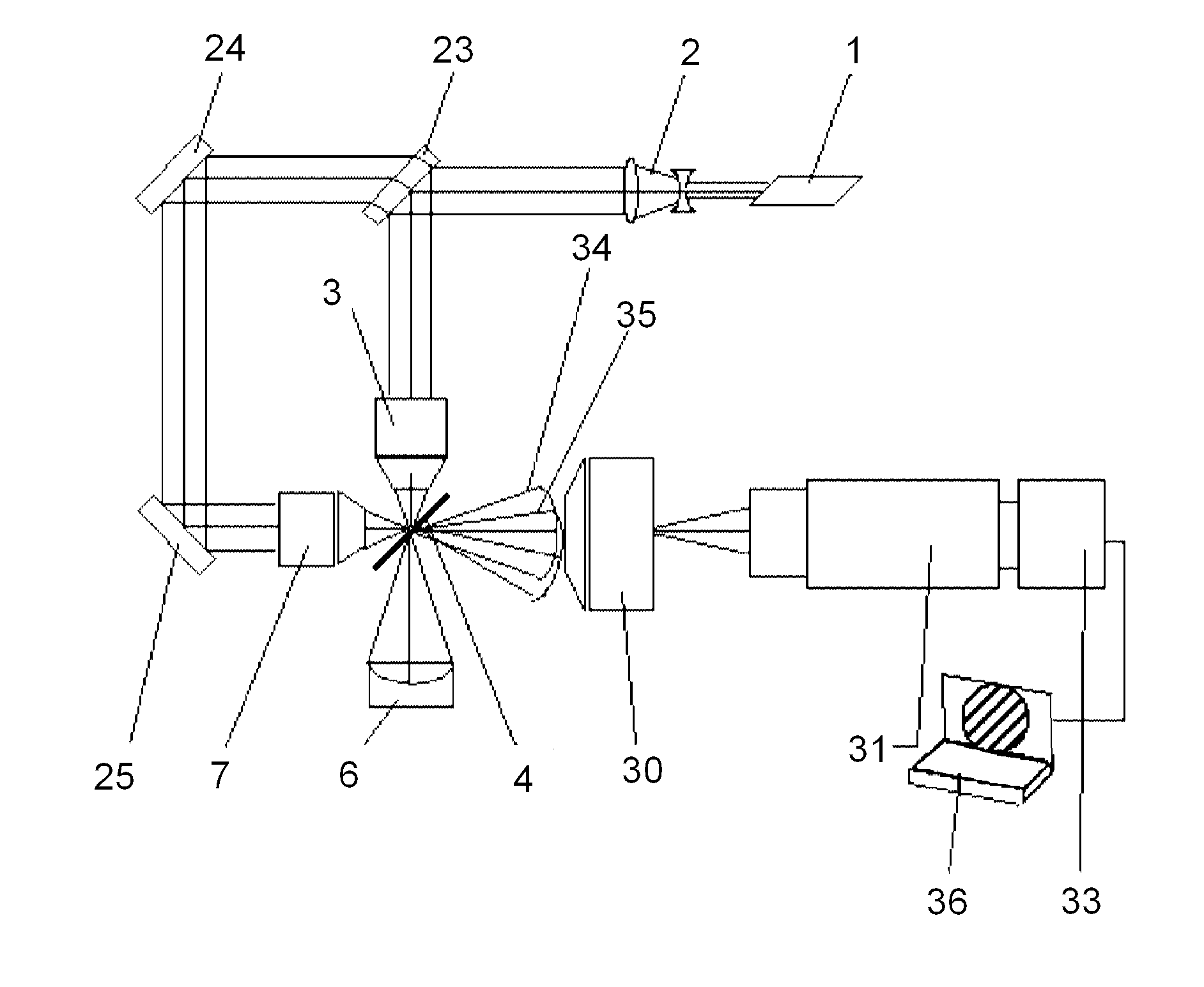
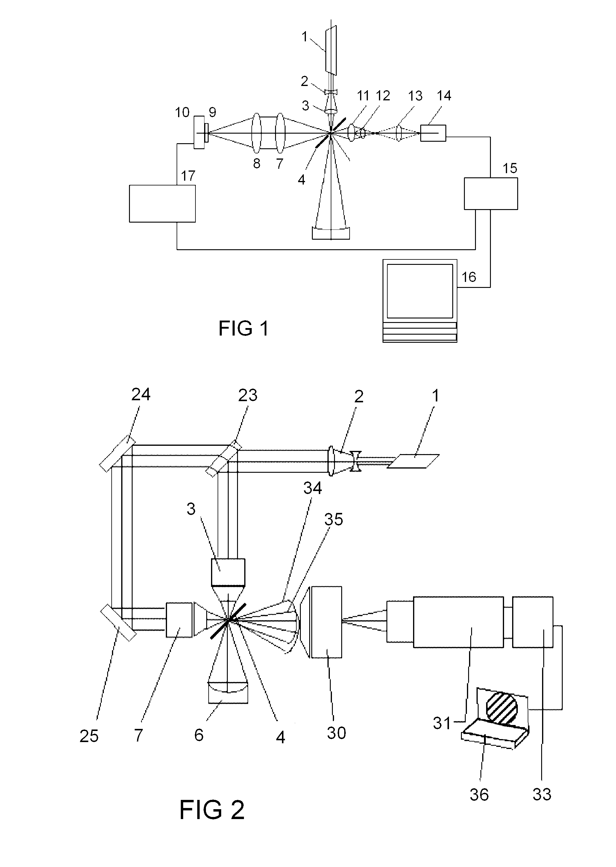
[0029]Following will be described the optical instrument—interferometer in details with references to the drawings where in the FIG. 2 is illustrated the interferometer according to the present invention working in the amplitude mode.

[0030]The details which are the same to the details of the prototype described above (see FIG. 1) have the same reference numbers.

[0031]The optical instrument (interferometer) comprises (see FIG. 2) the housing where are arranged: laser 1; beam expander 2, beam-splitter 23 in tunable mount; flat mirror 24, 25 in tunable mount; focusing objective 3, 7 in tunable mount; tested part or optical system 6; flat glass plate 4 with one side coated by thin metal highly reflecting coating with the pattern including a pinhole; observation objective 30; ZOOM system 31; computer 32; CCD camera 33. The interfering wavefronts 34, 35 will be originated to the objective 30.

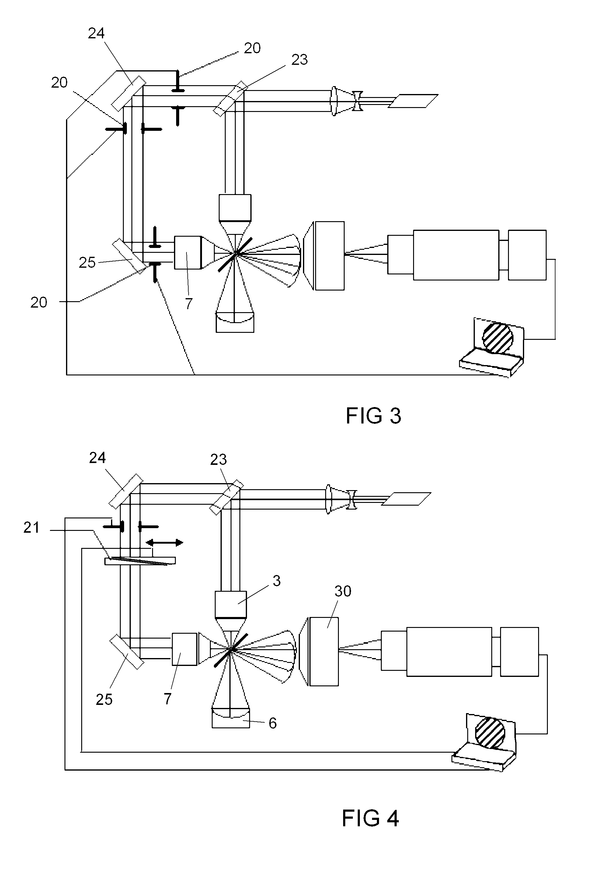
[0032]In another embodiment (see FIG. 3) of the present invention the interferometer contains in a...


PUM


Abstract

The present invention is related with the optical instrument such as interferometer for testing the optical systems and samples whereas the optical instrument comprises the laser (1) for generating the laser beam which passes the beam expander (2), beam-splitter (23) dividing the laser beam to a working light beam and reference light beam, focusing objectives (3, 7), flat glass plate (4) with one side coated by thin metal highly reflecting coating with the pattern including a pinhole, computer (12), CCD camera (13), tested part or optical system (6). In addition the optical instrument comprises at least two flat mirrors (24, 25), observation objective and at least one stop (20) placed between the beam-splitter (23), flat mirrors (24, 25) and/or focusing objective (7).

Description

TECHNICAL FIELD[0001]The present invention concerns the area of optical instrument making and can be used for testing optical systems and samples, including those having a high level of accuracy of correction of aberrations and errors, with deformations of wave front less than 1 / 90 wavelength, in particular the present invention is related with the interferometer for testing the optical systems and samples.BACKGROUND ART[0002]The closest prior art is the interferometer described in the document KR 20050102264 A (KOREA ELECTRO TECH RES INST) 26.10.2005. The named interferometer should be accepted as the prototype, intended for testing optical surfaces and optical systems.[0003]The above-mentioned interferometer (see FIG. 1, prior art) comprises: laser 1; elements of an objective of the illuminating system 2, 3; inclined flat mirror 4, in whose reflection coating there is a pinhole aperture 5, whose diameter is comparable with the wavelength of radiation passing through the interferom...

Claims


Application Information

Patent Timeline
IPC IPC(8): G01B9/02
CPCG01M11/005G01B9/02039G01M11/0271
Inventor VOZNESENSKAYA, MARIAKUZNETSOV, ALEKSEISUK, JUNG MEETSIKHANCHUK, HEORHI
Owner VTT NTM OU
Why Eureka
Try Eureka