Mixer assembly

a technology of mixing assembly and mixing chamber, which is applied in the direction of magnetic circuit rotating parts, magnetic circuit shape/form/construction, transportation and packaging, etc., can solve the problems of increasing stator current loss, reducing motor efficiency, and low power factor of asynchronous motors with a large number of poles, so as to reduce rotor losses and improve efficiency of permanent magnet motors , the effect of increasing the power factor

Inactive Publication Date: 2011-10-13
XYLEM IP HLDG
View PDF5 Cites 4 Cited by
  • Summary
  • Abstract
  • Description
  • Claims
  • Application Information

AI Technical Summary

Benefits of technology

[0012]In a preferred embodiment of the present invention, the annular radially inner section of the rotor core of the rotor of hybrid type comprises a number of permanent magnets. This means that when the hybrid rotor has been provided a rotating motion, the permanent magnets will take over from the rotor slots which results in the hybrid rotor will catch up and rotate synchronous with the rotating magnetic field of the stator, and the rotor slots will be inactive. Thus, after start up of the mixer, and during normal operation, the motor will operate as a synchronous motor. The efficiency of a permanent magnet motor is much higher due to reduced rotor losses, i.e. there is not any current in a rotor at synchronous speed and thus there are not any rotor current losses like in asynchronous motors. In the case with a large number of poles, the magnetizing current component of the stator current is also reduced, which lead to a higher power factor and thus decreased stator current losses.
[0013]According to a preferred embodiment, the annular radially inner section of the rotor core comprises a number of axially arranged V-shaped slots, which are oriented to be open radially outwards, each of the two outer ends of the V-shaped slot being ended adjacent and radially inside a rotor slot of the annular radially outer section of the rotor core, and being separated from said rotor slot by a material bridge of the rotor core. Preferably said material bridge is in the range 0.5-2 millimeters. Thereby the material bridge is too narrow for the magnetic field to leak there through and the material bridge will be saturated which further prevents the magnetic field to short cut from one pole to a neighboring pole.

Problems solved by technology

However, an asynchronous motor having a large number of poles has a low power factor, because a big stator current component is needed to magnetize the machine.
The increased stator current also lead to increased stator current losses and decreased motor efficiency.
The efficiency of a comparable prior art mixer comprising an asynchronous motor having a large number of poles is usually quite low for a given power output.
However, this entails that a larger stator housing is required which de facto results in that a new mixer is obtained, and not an improved mixer in respect of increased efficiency for a given power output for a specific mixer.
However, the increase in efficiency of an asynchronous motor of a specific mixer is not justifiable in relation to the increase in manufacturing cost.

Method used


Image

  • Mixer assembly
  • Mixer assembly
  • Mixer assembly

Examples


Embodiment Construction

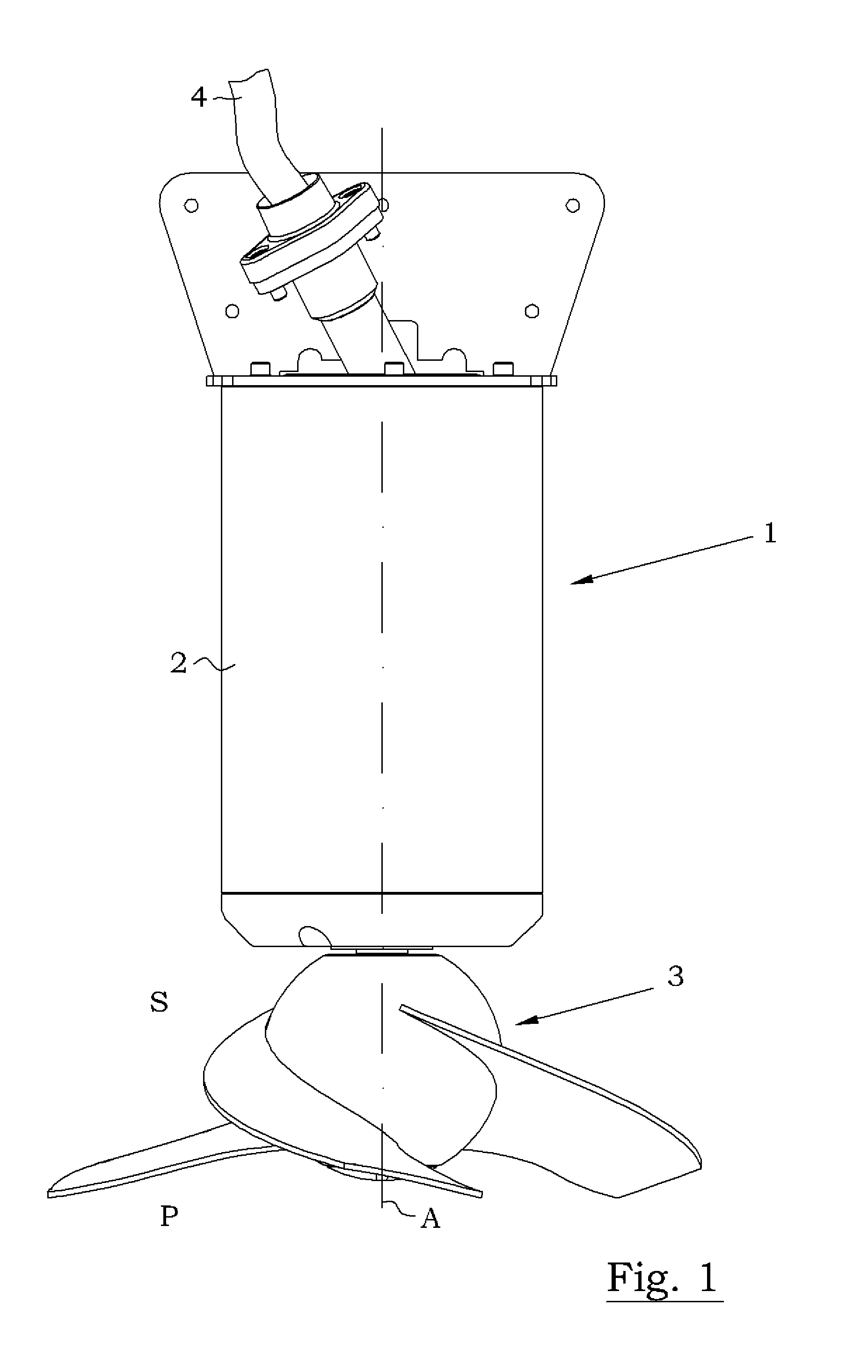
[0022]In FIG. 1 is shown a mixer 1, or mixer assembly. The mixer 1 comprises a housing 2, also known as stator housing, and a propeller 3 having a suction side S and a pressure side P. An electric cable 4 extends from the mixer 1 and is arranged to be connected directly to the power mains, i.e. the mixer 1 does not need any variable frequency drive (VFD) or the like to ramp up the stator current at the start of the mixer 1. Such a mixer 1 is also known as a line started mixer.

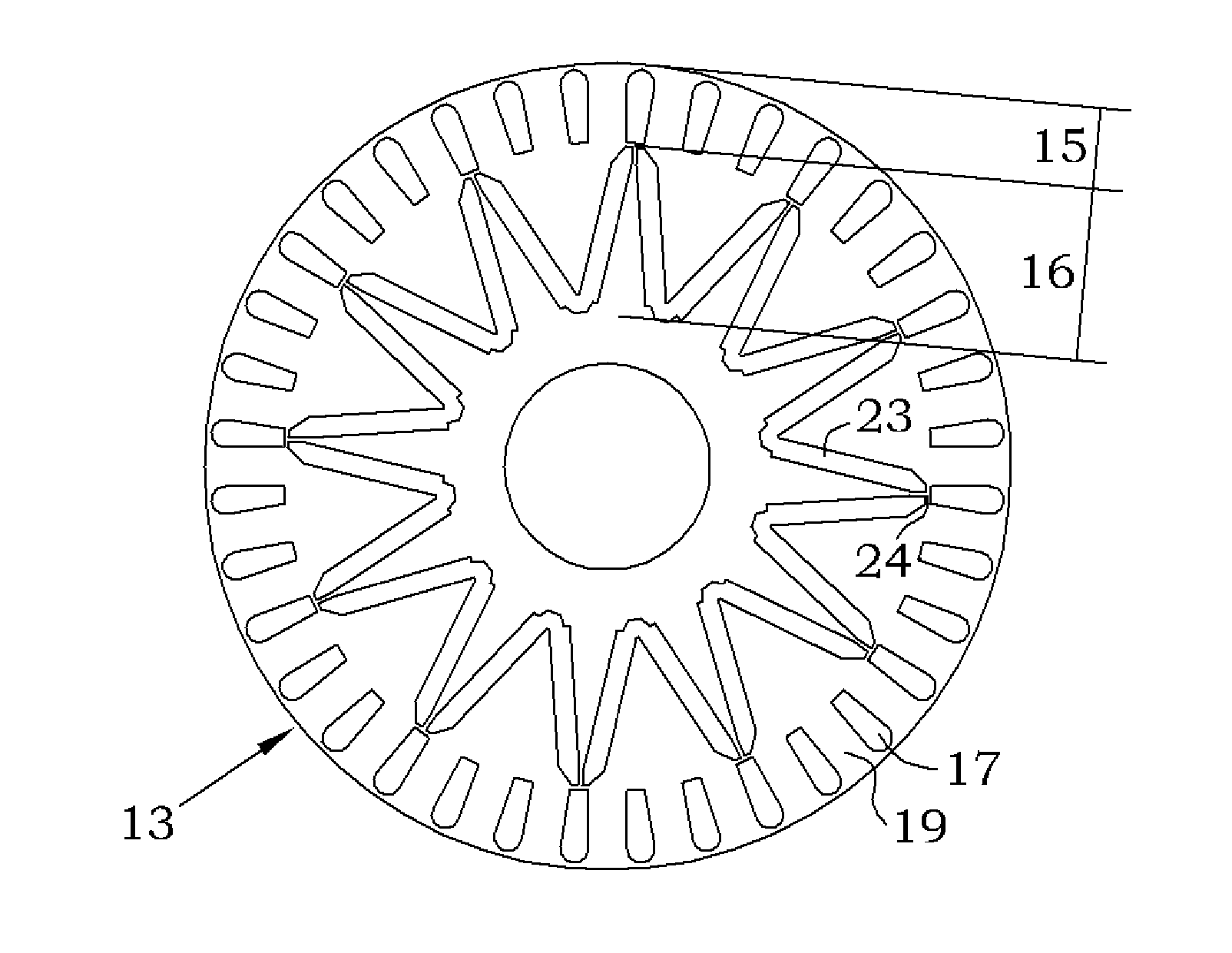
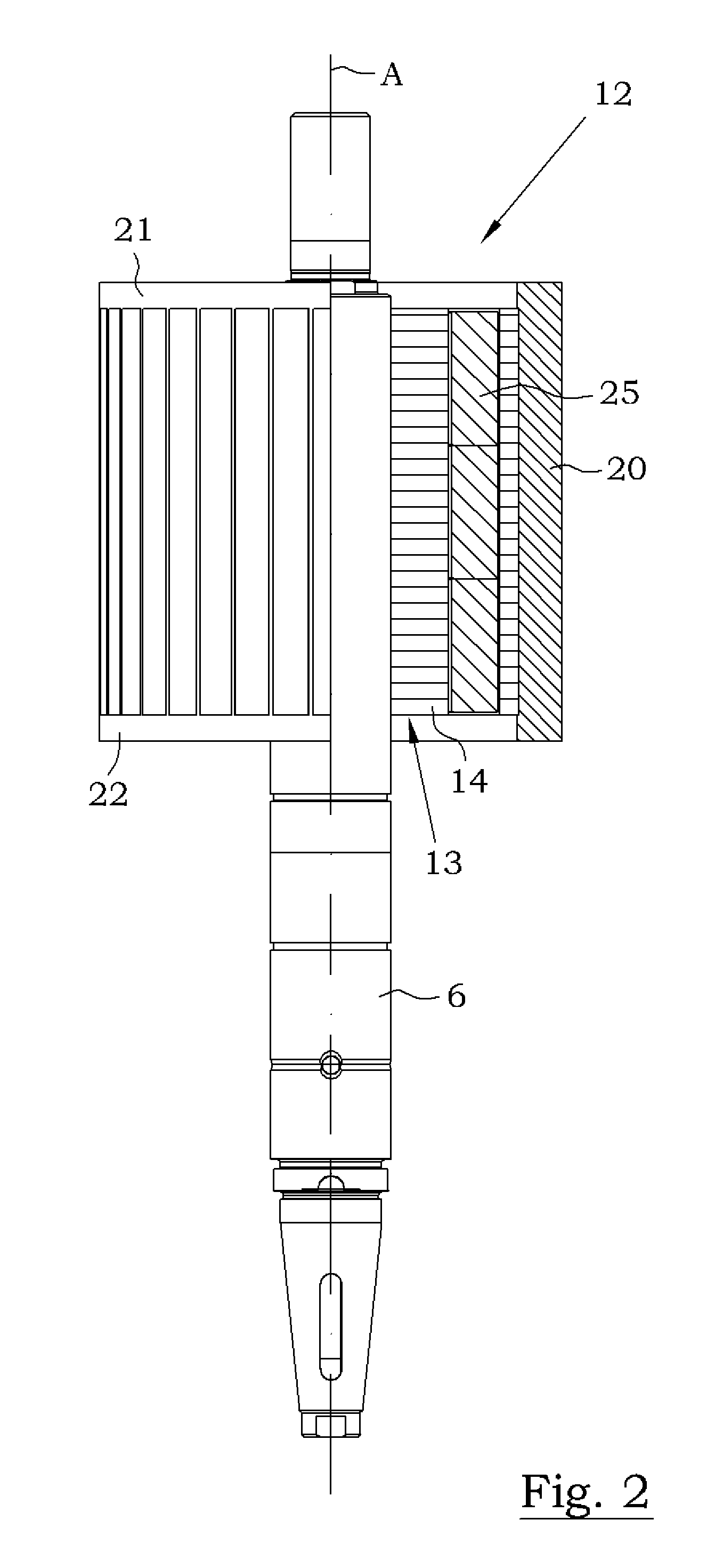
[0023]Reference is now made to FIGS. 2 and 3. The mixer 1 comprises a motor, generally designated 5, and a drive shaft 6 extending from said motor 5 to the propeller 3 of the mixer 1, i.e. the propeller 3 is fitted to the lower end of the drive shaft 6. The propeller 3 in operation is driven by the motor 5 for rotation about a propeller axis A in order to generate a liquid flow from the suction side S to the pressure side P of the propeller 3. The propeller 3 comprises a hub and one or more vanes extending from...


PUM


Abstract

A mixer assembly for generating and maintaining a motion within a volume of liquid, the mixer assembly including a motor, a drive shaft and a propeller connected to the drive shaft. When the propeller is in operation, it is driven by the motor and rotates about a propeller axis. The mixer assembly's motor comprises a stator and a hybrid type rotor. The hybrid rotor includes a rotor core comprising an annular radially outer section of asynchronous type and an annular radially inner section of synchronous type arranged radially inside the annular radially outer section.

Description

CROSS REFERENCE TO RELATED APPLICATIONS[0001]This application is the U.S. national phase application of PCT International Application No. PCT / SE2009 / 051206, filed Oct. 22, 2009, which claims priority to Swedish Patent Application No. 0850051-4, filed Oct. 23, 2008, the contents of such applications being incorporated by reference herein.FIELD OF THE INVENTION[0002]The present invention relates generally to the field of devices arranged to be submersed into a liquid and operable for stirring the liquid by means of a propeller, which is driven in rotation. Further, the present invention relates specifically to the field of mixer assemblies for generating and maintaining a motion within a volume of liquid, e.g. waste water. The mixer assembly comprises a motor, a propeller and an intermediate drive shaft connected to said motor and propeller, the propeller in operation being driven by the motor for rotation about a propeller axis in order to generate a liquid flow from a suction side t...

Claims


Application Information

Patent Timeline
Patent Type & Authority Applications(United States)
IPC IPC(8): H02K21/46B01F7/22B01F27/71B01F27/91H02K1/276
CPCH02K1/2766H02K21/46H02K17/165H02K1/27H02K1/276
Inventor WAND, KATRINMOKANDER, JURGENLINDEBORG, ROLFENGSTROM, JORGENHEDBERG, TANJABARTHOLF, THOMAS
Owner XYLEM IP HLDG
Why Eureka
Try Eureka