

Roller-type dual cosmetic case having airless pump
a dual-purpose, airless technology, applied in the direction of single-use apparatus, packaged goods type, packaging foodstuffs, etc., can solve the problems of reducing preservation ability, affecting the appearance of external objects, so as to improve the structure of the roller-type dual-purpose cosmetic case, convenient and safe storage and use, and improve the effect of the structur
- Summary
- Abstract
- Description
- Claims
- Application Information
AI Technical Summary
Benefits of technology
Problems solved by technology
Method used
Image

Examples
Embodiment Construction
[0026]Hereinafter, a preferred embodiment of the present invention will be described with reference to the accompanying drawings. In the following description of the present invention, a detailed description of known functions and configurations incorporated herein will be omitted when it may make the subject matter of the present invention rather unclear.
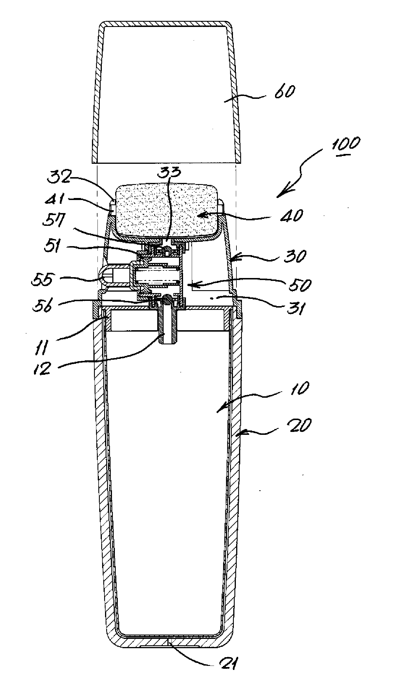
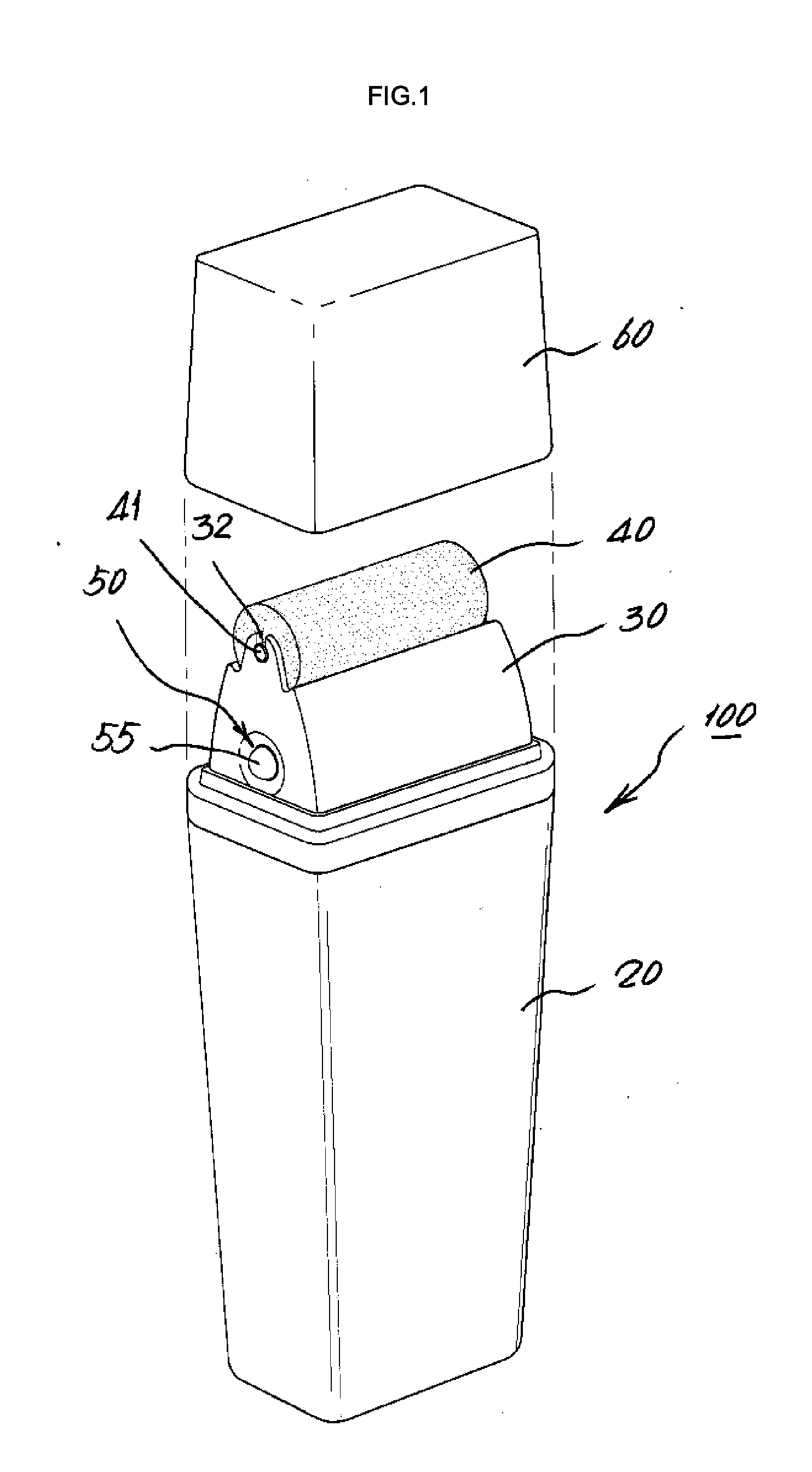
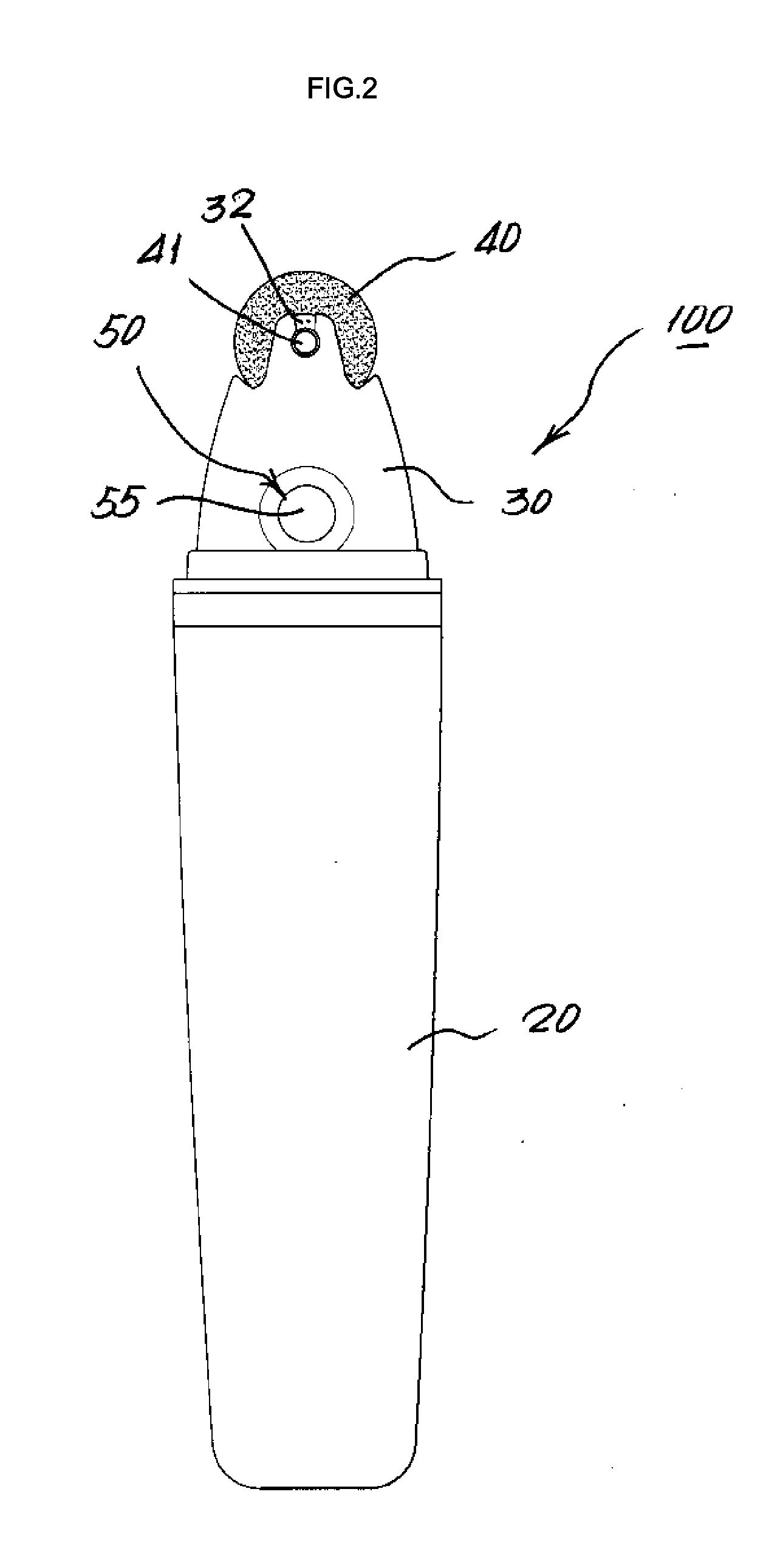
[0027]FIGS. 1 and 2 show an overall structure of an outward shape of a roller-type dual cosmetic case to which the invention is applied, FIGS. 3 and 4 specifically show an inside structure of a roller-type dual cosmetic case according to the invention and FIGS. 5 to 7 show a detailed structure of the invention.
[0028]In Figs., a reference numeral 100 indicates a main body of a roller-type dual cosmetic case according to the invention, which comprises a tube-type inner case 10 made of a flexible material and storing a variety of cosmetics, a rigid outer case 20 provided to an outside of the inner case to form a dual structure and pro...
PUM
 Abstract
Description
Claims
Application Information