
Ophthalmological laser system and operating method

Active Publication Date: 2011-10-13
CARL ZEISS MEDITEC AG
View PDF8 Cites 35 Cited by
  • Summary
  • Abstract
  • Description
  • Claims
  • Application Information

AI Technical Summary

Benefits of technology

[0012]The invention is based on the task of improving an ophthalmological laser system and a corresponding operating method of the initially mentioned type in such a way that a laser-supported surgical procedure within the course of a keratoplasty is made possible with greater accuracy, whereby improved chances for success and a decreased treatment risk are to be achieved and / or that an easier manual detachment of perforated tissue components is made possible.

Problems solved by technology

Disadvantageously, said method requires two laser systems.
During keratoplasty (refractive correction, transplant), the shape of the cornea of the human eye is problematic.
In addition, further irregularities of the corneal thickness can occur with certain pathologies.
Therefore, the accuracy of the laser treatment, as far as it is based on the measured shape, is limited.
As a result, the transplant can deviate from its planned shape and not be implanted optimally in the recipient's eye.
This can lead to complications, e.g., the detachment of the transplant or glaucoma due to a shift of the transplant.
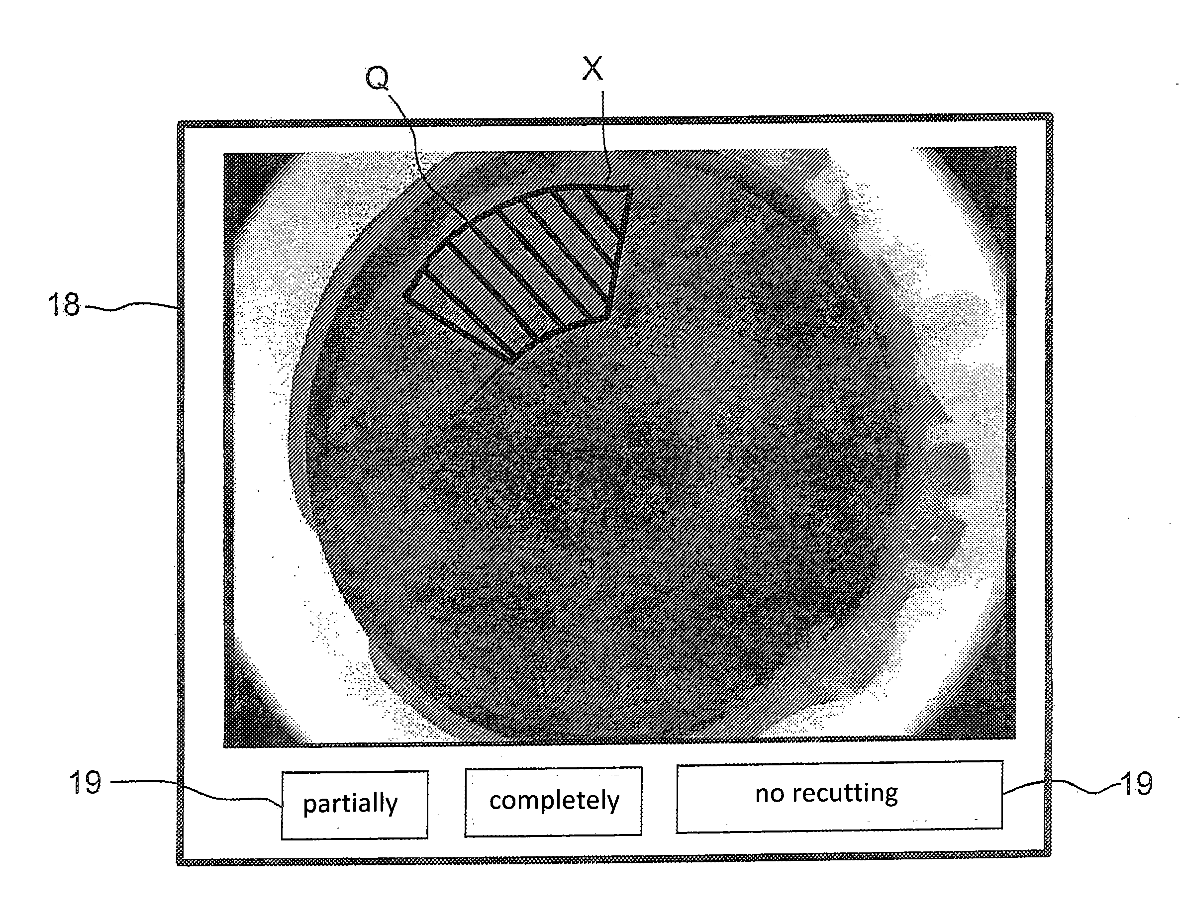
Regardless of the shape of the cornea, there is also the problem that in some cases optically opaque bubbles (opaque bubble layer—OBL) may appear during the perforation of corneal tissue by means of femtosecond laser radiation with lamellar incisions.
Depending on position and characteristic of an OBL field, the perforation of the tissue in this area is not ideal.
In comparison to the surrounding area, the result is a more difficult manual detachment of the tissue components to be separated, which leads to tissue stress and / or to a prolonged duration of surgery.
Furthermore, modifications of the incision geometry and gas pockets are disadvantageous with regard to the preservation of as much residual stromal thickness as possible.

Method used


Image

  • Ophthalmological laser system and operating method
  • Ophthalmological laser system and operating method
  • Ophthalmological laser system and operating method

Examples


Embodiment Construction

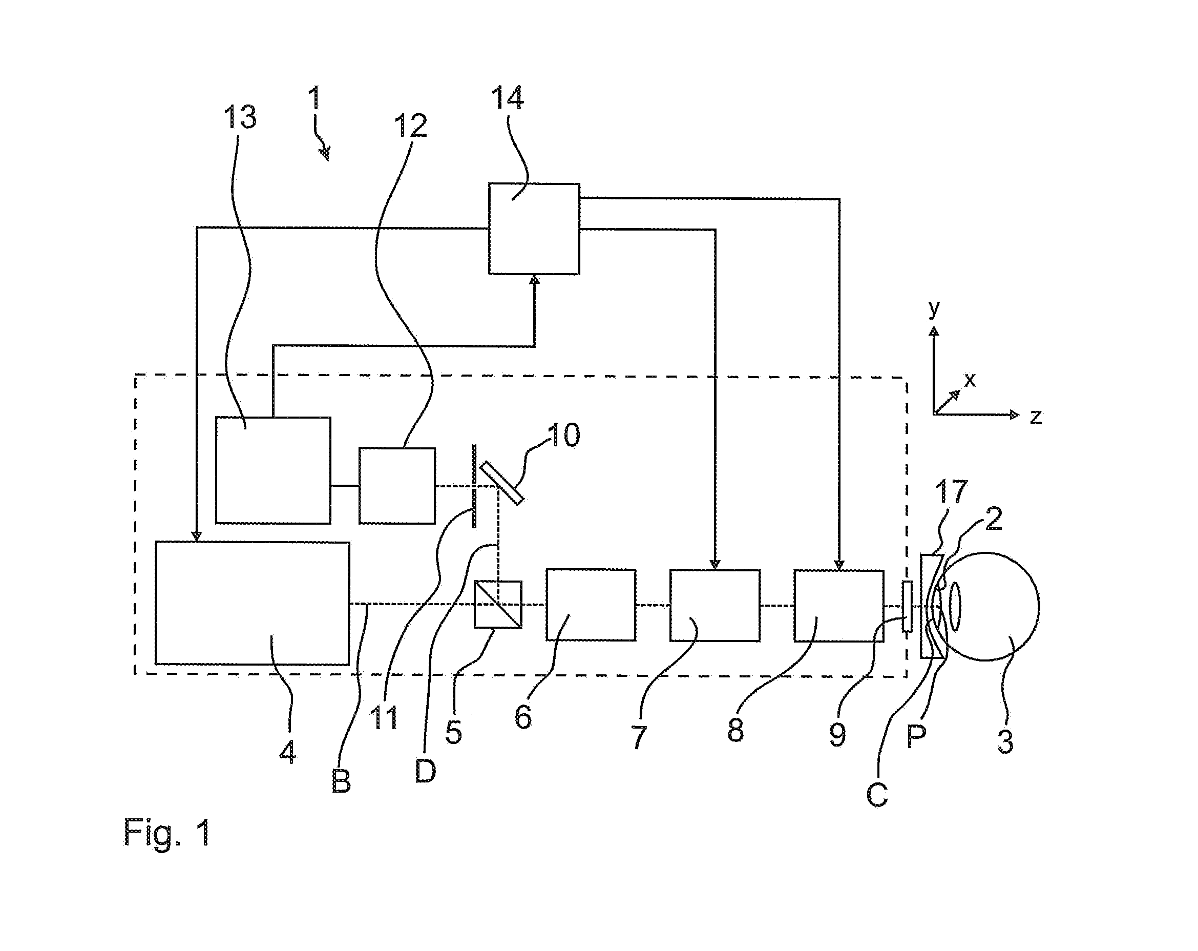
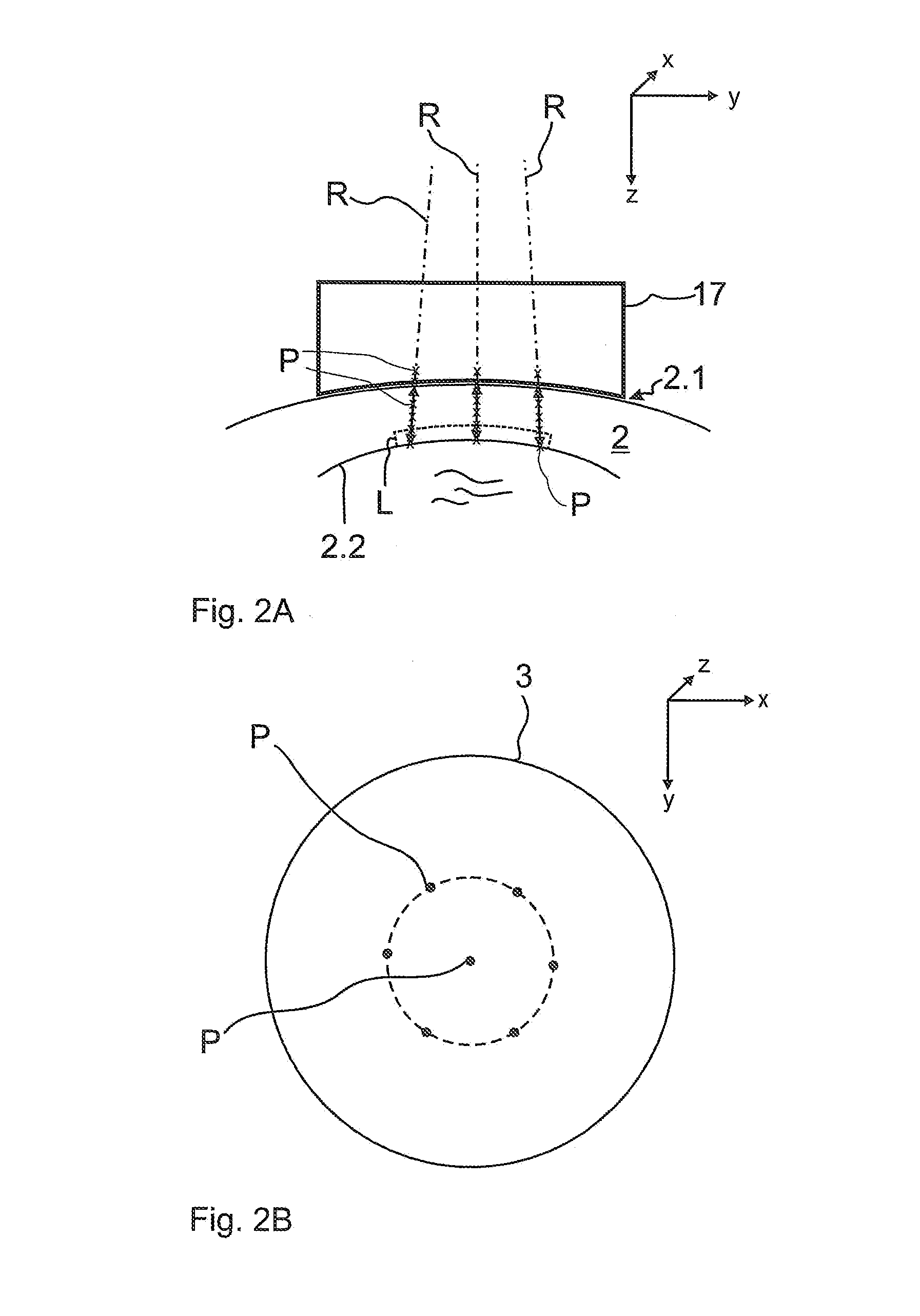
[0066]FIG. 1 shows an exemplary ophthalmological laser system 1 for identification and localization of the posterior boundary layer of a cornea 2 of an eye 3 with regard to form and position of the boundary layer. The laser system 1 comprises a laser 4, a polarization beam splitter 5, scan optics 6, a scanner unit 7, focusing optics 8, and an optical phase retardation system 9, which together form an illumination beam path B; as well as a deflection mirror 10, a confocal aperture diaphragm 11, and a detector 12, which form a decoupled detection beam path D. In addition, the laser system 1 comprises an amplifier 13 and a control unit 14. Between the laser system 1 and the eye 3, an immobilization device 17 with a contact glass for the eye 3 is positioned, behind which lies the examination region. On the side facing the eye 3, the contact glass can exhibit a spherical, planar, eye-curved, or any other surface rotationally symmetric around the optical axis. This example shows a spheric...


PUM


Abstract

An ophthalmological laser system and operating method wherein laser-supported operative interventions can be achieved with higher accuracy. The cornea is irradiated with an ophthalmological laser and a detection light confocally recorded, the cornea being scanned in three-dimensions by irradiation with an illuminating laser power using a scanner unit along several directions at several points. Using the simultaneously recorded detection light the position and / or shape of a posterior boundary surface of the cornea is determined. A lamella parallel to the posterior boundary surface can then be cut.

Description

PRIORITY CLAIM[0001]The present application is a National Phase entry of PCT Application No. PCT / EP2009 / 067354, filed Dec. 16, 2009, which claims priority from German Application No 102008062658.9, filed Dec. 17, 2008, the disclosures of which are hereby incorporated by reference herein in their entirety.FIELD OF THE INVENTION[0002]The invention relates to an ophthalmological laser system with a laser, the radiation of which is focusable in an examination region via an illumination beam path, which exhibits a scanner unit; particularly with an immobilization device for an eye positioned in the examination region. Furthermore, the invention relates to an operating method for an ophthalmological laser system.BACKGROUND[0003]In ophthalmology it has been established, in case of defective vision, to form the cornea of the human eye with its approximate thickness of 500 μm through ablation of tissue in order to correct myopia, hypermetropia, and astigmatism. This is called refractive surg...

Claims


Application Information

Patent Timeline
IPC IPC(8): A61F9/008
CPCA61F9/00831A61F2009/00897A61F2009/00872
Inventor BISSMANN, WILFRIEDVOGELSANG, HARTMUTSTOBRAWA, GREGORBARTELS, ANDREAS
Owner CARL ZEISS MEDITEC AG
Learn More