Needle-coupled parallel mechanism

a parallel mechanism and needle technology, applied in the direction of prosthesis, application, gearing, etc., can solve the problems of increasing the force necessary to control the posture and position of the needle, low precision of the serial mechanism, etc., and achieve the effect of high precision and wide working area

Active Publication Date: 2011-10-13
IUCF HYU (IND UNIV COOP FOUNDATION HANYANG UNIV)
View PDF4 Cites 19 Cited by
  • Summary
  • Abstract
  • Description
  • Claims
  • Application Information

AI Technical Summary

Benefits of technology

[0008]The present invention has been made in view of the above problems, and it is an object of the present invention to provide a structurally improved needle-coupled parallel mechanism that has a broad working area and a high precision.

Problems solved by technology

For example, the needle reflects cumulative errors generated in the respective links in the course of controlling the posture and position of a needle, resulting in a very low precision of the serial mechanism.
Further, the links coupled in series inevitably increase the size and inertial mass of the serial mechanism, which greatly increases the force necessary to control the posture and position of the needle.

Method used


Image

  • Needle-coupled parallel mechanism
  • Needle-coupled parallel mechanism
  • Needle-coupled parallel mechanism

Examples


Embodiment Construction

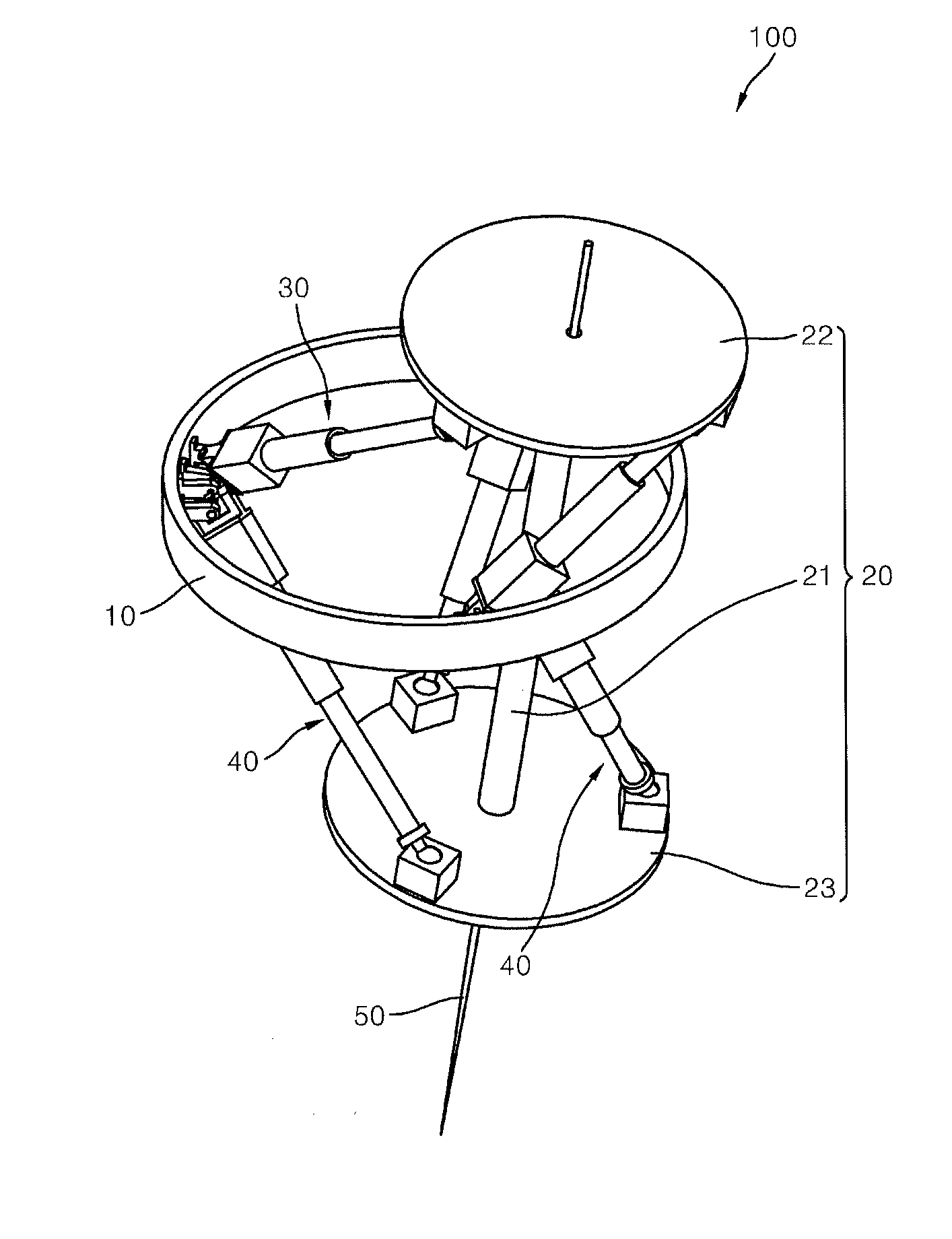
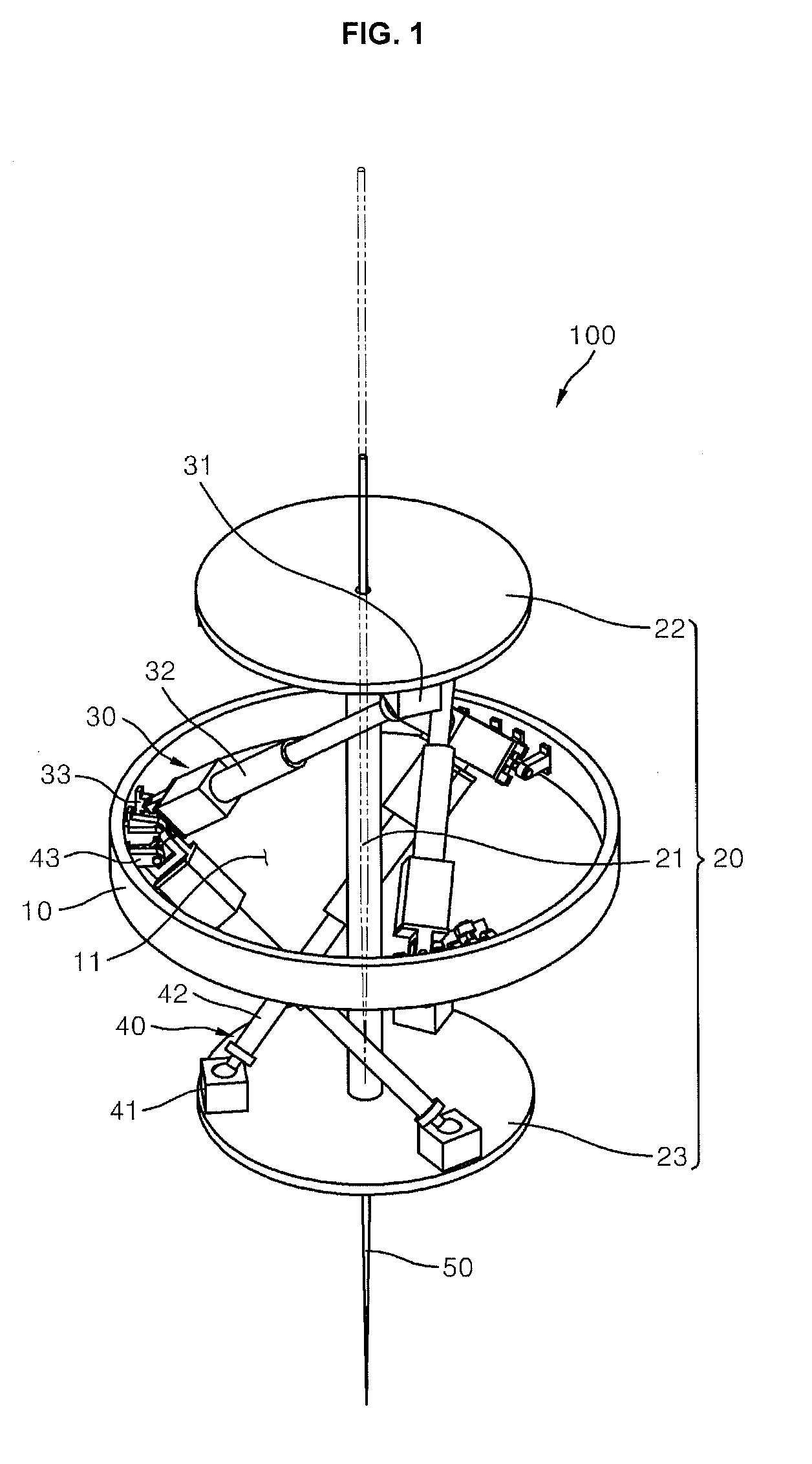
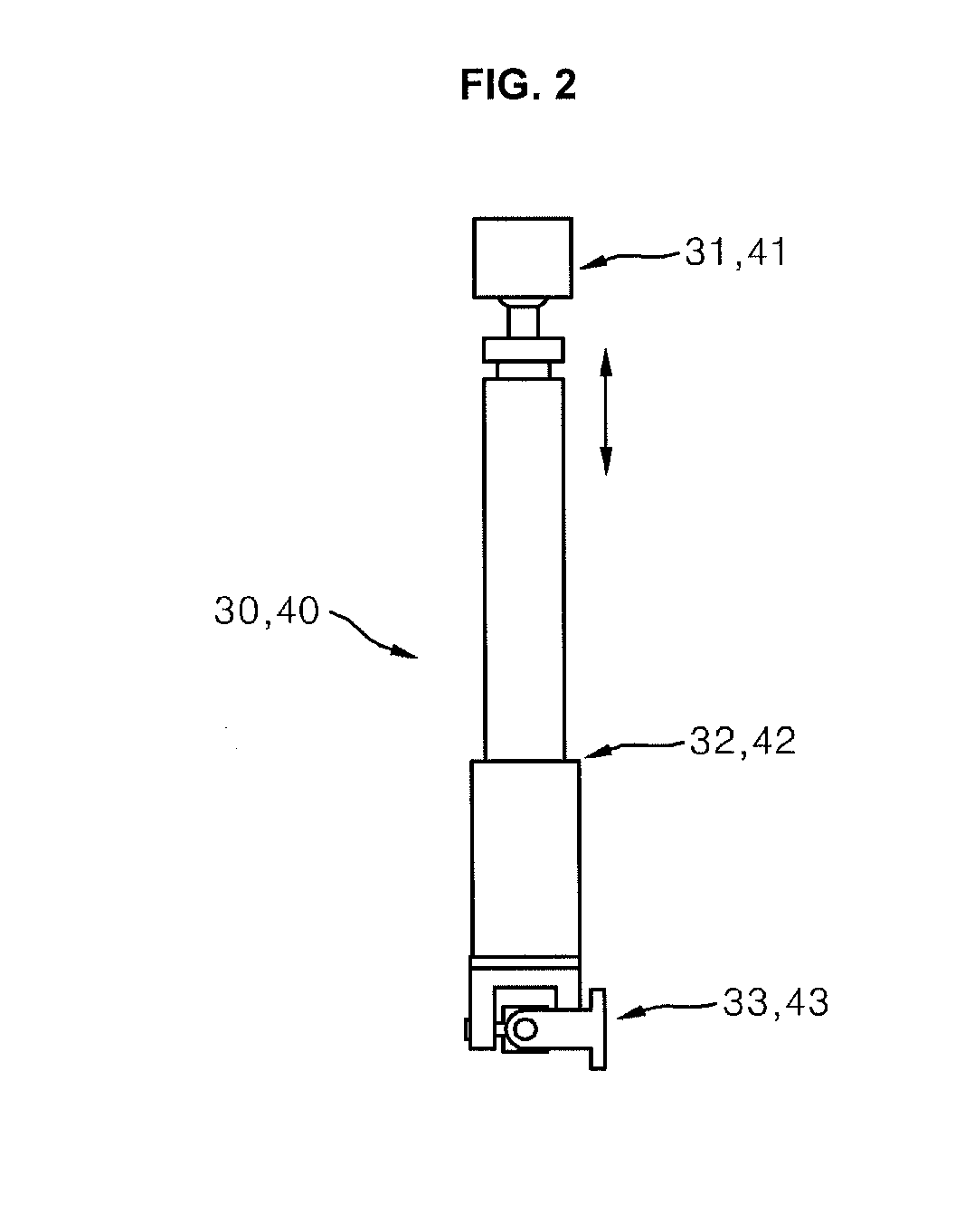
[0017]FIG. 1 is a perspective view of a needle-coupled parallel mechanism according to an embodiment of the present invention, FIG. 2 is a conceptual view of a first link or a second link of the needle-coupled parallel mechanism, and FIGS. 3 and 4 are perspective views for explaining the operation of the needle-coupled parallel mechanism.

[0018]Referring to FIGS. 1 through 4, the needle-coupled parallel mechanism 100 comprises a parallel mechanism and a needle 50 coupled to the parallel mechanism.

[0019]The parallel mechanism serves to control the posture and position of the needle 50. The parallel mechanism includes a frame 10, a main shaft 20, first links 30, and second links 40.

[0020]One end of each of the first links 30 and the second links 40 is fixed to the frame 10. An explanation of the first links 30 and the second links 40 will be provided below. No limitation is imposed on the shape of the frame 10 so long as one end of each of the first links 30 and the second links 40 can...


PUM


Abstract

A needle-coupled parallel mechanism is provided. The needle-coupled parallel mechanism is structurally improved so as to have a broad working area and a high precision. The needle-coupled parallel mechanism comprises a fixedly positioned frame, a main shaft, three first links, three second links, and a needle. The main shaft is arranged so as to be movable relative to the frame. One end of each of the first links is connected to the frame between both ends of the main shaft and the other end thereof is connected to one end of the main shaft. One end of each of the second links is connected to the frame between both ends of the main shaft and the other end thereof is connected to the other end of the main shaft. The needle is linearly movably coupled to the main shaft to perform a predetermined operation on a target object. Each of the first links and the second links has at least three joints selected from a prismatic joint, a 1-axis revolute joint, a 2-axis revolute joint and a spherical joint. The needle and the main shaft are moved with 6 degrees-of-freedom in conjunction with the operations of the first links and the second links.

Description

BACKGROUND OF THE INVENTION[0001]1. Field of the Invention[0002]The present invention relates to a needle-coupled parallel mechanism that performs an operation on a target object while controlling its position and posture in a three-dimensional space.[0003]2. Description of the Related Art[0004]In recent years, many medical devices have been developed for various medical purposes, for example, biopsy and drug infusion into living bodies. A typical example of such medical devices consists of a needle inserted into a living body to perform a medical function, such as drug infusion or tissue sampling, and a mechanism coupled to the needle to control the posture and position of the needle.[0005]The size of and the precision in the working area of the medical device are important factors in determining the performance of the medical device. The size of the working area means the size of the area where the position and posture of the needle are controllable, and the precision in the worki...

Claims


Application Information

Patent Timeline
Patent Type & Authority Applications(United States)
IPC IPC(8): A61B19/00
CPCY10T74/1824A61B17/3403A61B19/201A61B2017/3409A61M5/3287A61B90/11
Inventor YI, BYUNG-JULIM, HOONLEE, SANG-HEON
Owner IUCF HYU (IND UNIV COOP FOUNDATION HANYANG UNIV)
Why Eureka
Try Eureka