Method of optimising energy consumption

a technology of energy consumption and energy consumption, applied in the direction of instruments, pulse techniques, static/dynamic balance measurement, etc., can solve the problem that the same intelligent control technique may be very ineffective, and achieve the effect of high accuracy, high probability of accuracy, and optimising energy consumption

Inactive Publication Date: 2011-10-13
LIGHTWAVE TECH
View PDF3 Cites 63 Cited by
  • Summary
  • Abstract
  • Description
  • Claims
  • Application Information

AI Technical Summary

Benefits of technology

[0021]By carrying out such a method, it is possible to determine which of the intelligent control techniques was most accurate historically for a given set of weather conditions. It may be found that one particular intelligent control technique was highly accurate during winter months when snow was forecast. Therefore, this intelligent control technique may be preferred when the same weather conditions are being experienced.
[0022]In a further embodiment of the invention there is provided a method of optimising energy consumption in which the step of determining the appropriate control input for the BMS comprises using the intelligent control technique that is determined to be the most accurate for those conditions. Alternatively, the step of determining the appropriate control input for the building management system comprises generating a control input from a weighted average of a plurality of the intelligent control techniques with the weighting based on their historical accuracy. In other words, it is possible to take either the most accurate intelligent control technique response or to use a weighted average of a plurality of the intelligent control techniques so that an average result is taken with a high probability of accuracy.
[0023]In another embodiment of the invention there is provided a method of optimising energy consumption in a building in which the step of determining the accuracy of the intelligent control techniques further comprises minimisation of the error of each of the intelligent control techniques. By this, what is meant is determining the relative accuracy of the intelligent control up to a certain tower bound to avoid over-fitting or under-fitting of the model. This further avoids the possibility of over-training or under-training the neural networks. This is seen as a particularly efficient way of determining the accuracy of the intelligent control techniques and assisting in the selection of the appropriate intelligent control technique and hence the appropriate control input for the BMS.
[0024]In one embodiment of the invention there is provided a method of optimising energy consumption in a building in which the step of providing the appropriate control input to the BMS further comprises providing one or more of an optimal start time, an optimal stop time and a setpoint control.

Problems solved by technology

However, the same intelligent control technique may be very ineffective during summer months.

Method used


Image

  • Method of optimising energy consumption
  • Method of optimising energy consumption
  • Method of optimising energy consumption

Examples


Embodiment Construction

[0044]The invention will be more clearly understood from the following description of some embodiments thereof, given by way of example only, with reference to the accompanying drawings, in which:—

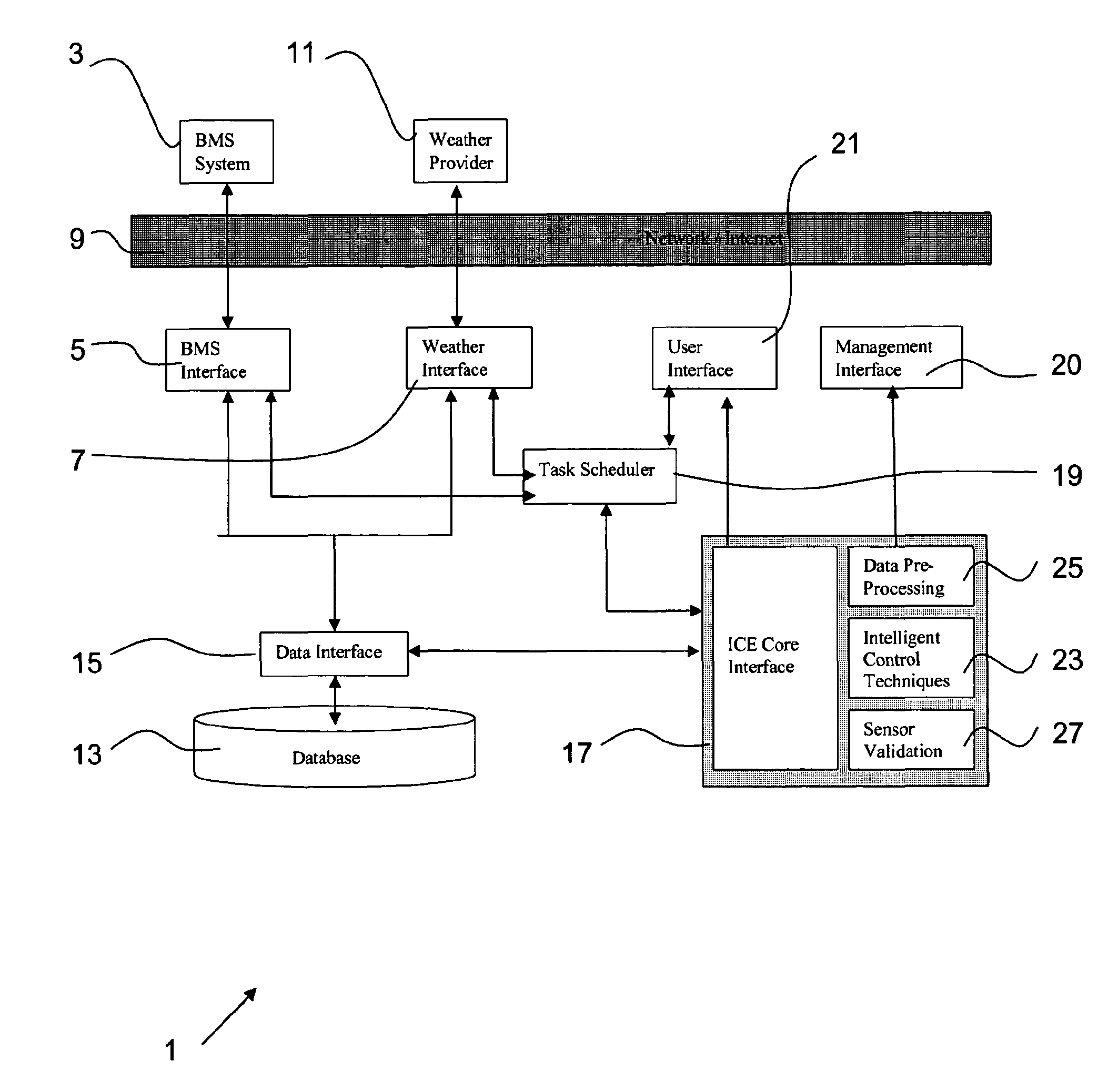
[0045]FIG. 1 is a diagrammatic representation of the overall architecture of the controller used to carry out the method according to the invention;

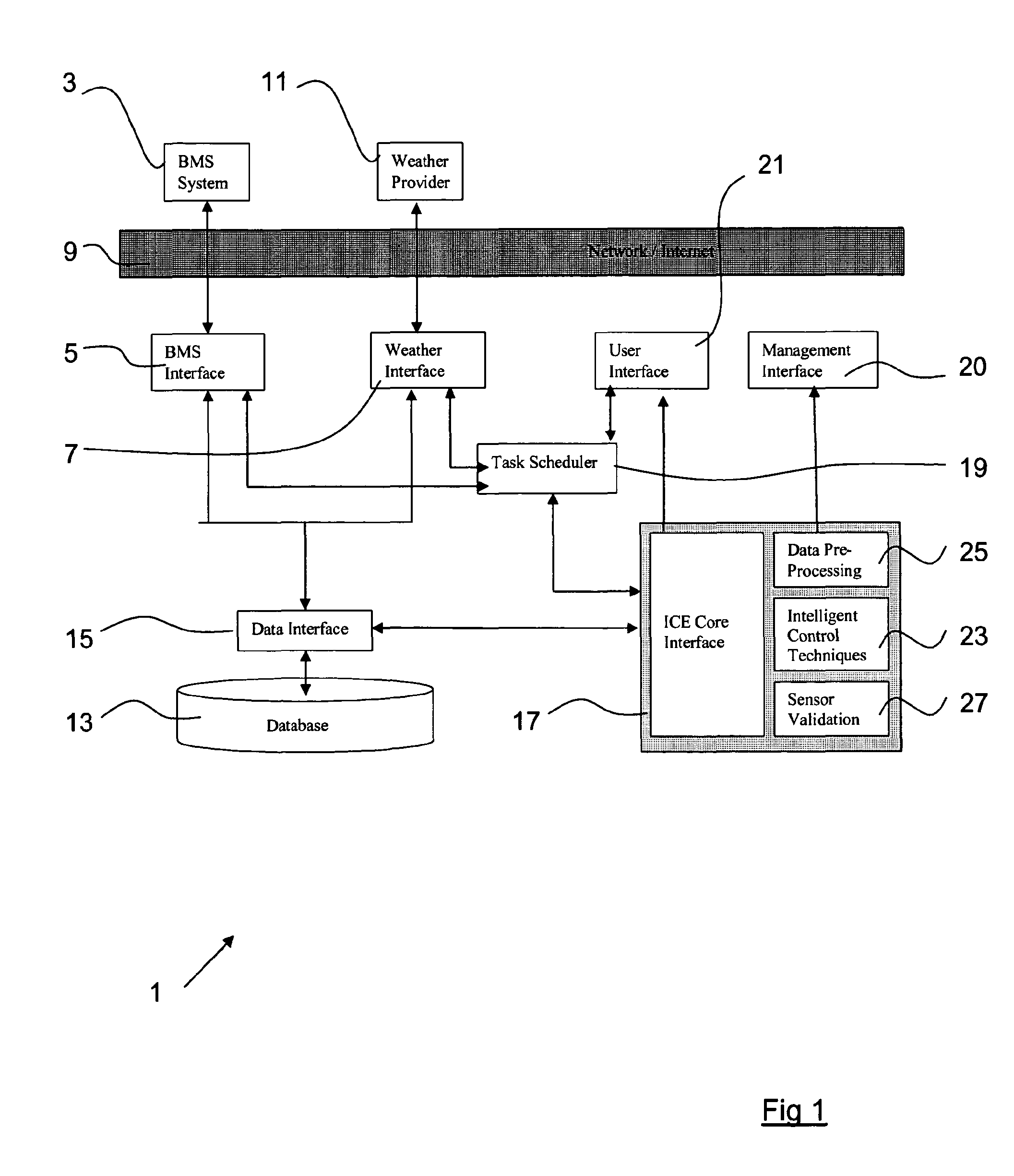
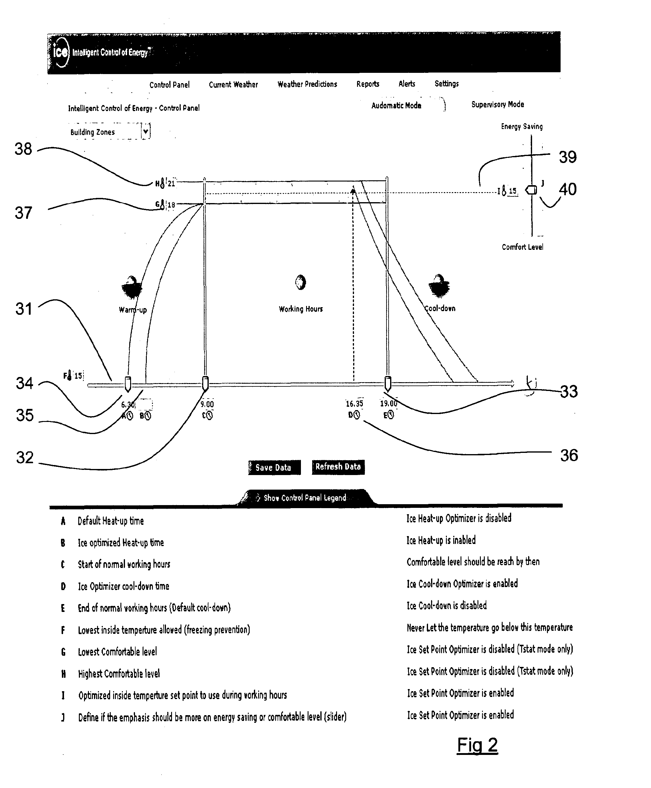
[0046]FIG. 2 is a diagrammatic representation of a control panel used with the controller of the present invention;

[0047]FIG. 3 is a block diagram of a plurality of adaptive deciders in cascaded format used by the controller;

[0048]FIG. 4 is a flow diagram of the energy prediction and optimisation agents;

[0049]FIG. 5 is a diagrammatic representation of a predictor / optimiser neural network with genetic algorithms;

[0050]FIG. 6 is diagrammatic representation of a predictive recursive optimal control unit for use with the controller of the present invention; and

[0051]FIG. 7 is a diagrammatic representation of a zone in a building in which the method...


PUM


Abstract

This invention relates to a method and controller (1) for optimising energy consumption in a building. More specifically, the present invention describes a method and controller (1) for use in a building having a building management system (BMS) (3). Typically, the BMS (3) has sensors distributed throughout the building to determine the environmental conditions in the building and the BMS controls a heating/cooling system of the building.

Description

INTRODUCTION[0001]This invention relates to a method of optimising energy consumption in a building having a building management system (BMS), the BMS being used to monitor the environmental conditions of the building and control the heating and / or cooling system of the building. This invention further relates to a controller for carrying out such a method.[0002]Throughout this specification, reference is made to a heating system. However, it will be understood that the heating system may be used to increase the temperature in a building and also may be used to decrease the temperature in a building, operating effectively as a cooling system. However, for simplicity, reference is made predominantly to a heating system and it will be understood that this invention applies equally to a cooling system and where reference is made to a heating system this is deemed to include a cooling system also. Furthermore, throughout the specification the invention is described with respect to a bui...

Claims


Application Information

Patent Timeline
Patent Type & Authority Applications(United States)
IPC IPC(8): G05D23/19G06F1/32G06N7/02G06N3/12G06N3/02
CPCG05B13/0285G05B13/0265F24F11/30F24F2130/00F24F2130/10F24F11/62F24F11/58F24F11/46
Inventor MCNULTY, NICHOLASPACKHAM, IANVANDERSTOCKT, YANN DANIEL EDGARDHAGRAS, HANIBYRNE, MARTIN
Owner LIGHTWAVE TECH
Why Eureka
Try Eureka