Supercharge Your Innovation With Domain-Expert AI Agents!

Pump

a technology for pumping and nozzles, applied in the field of pumps, can solve the problems of limited rotation of the whole air output piping, difficulty in connecting the nozzle, and the large volume of the floor pump, and achieve the effect of increasing the overall length of the air output piping of the pump

Inactive Publication Date: 2011-10-20
HUANG YING CHE
View PDF11 Cites 14 Cited by
  • Summary
  • Abstract
  • Description
  • Claims
  • Application Information

AI Technical Summary

Benefits of technology

"The present invention is a pump with a barrel and a top cap. It also includes an adapter with a channel and a pivotal end. A piston rod is connected to the pivotal end and extends into the barrel. A piston is mounted at the end of the piston rod. A hose is connected to the other end of the channel and includes a coupling seat with an inner thread. A connecting block is positioned on the side of the barrel. The invention also includes two rotary inflation nozzles with different specifications and identical size. One of the nozzles can be inserted into the barrel and the other nozzle has a positioning portion. The overall length of the air output piping of the pump can be increased by using the hose with dual inflation nozzles. The technical effect of this invention is to provide a versatile pump that can be used with different types of valves and to increase the air output piping length."

Problems solved by technology

Although the floor pump allows stable operation by stepping on the pedal and has a larger size to provide larger air output, the bulky volume of the floor pump requires a larger space for storage and is not easy to carry due to heavy weight.
Furthermore, the rigid outer pipe 34 is inflexible and can only be rotated in a single direction even though the inner hose 35 is flexible, resulting in limitation to the rotation of the whole air output piping and, hence, difficulties in connecting the nozzle 36 with the valve of the tire.

Method used


Image

  • Pump
  • Pump
  • Pump

Examples


Embodiment Construction

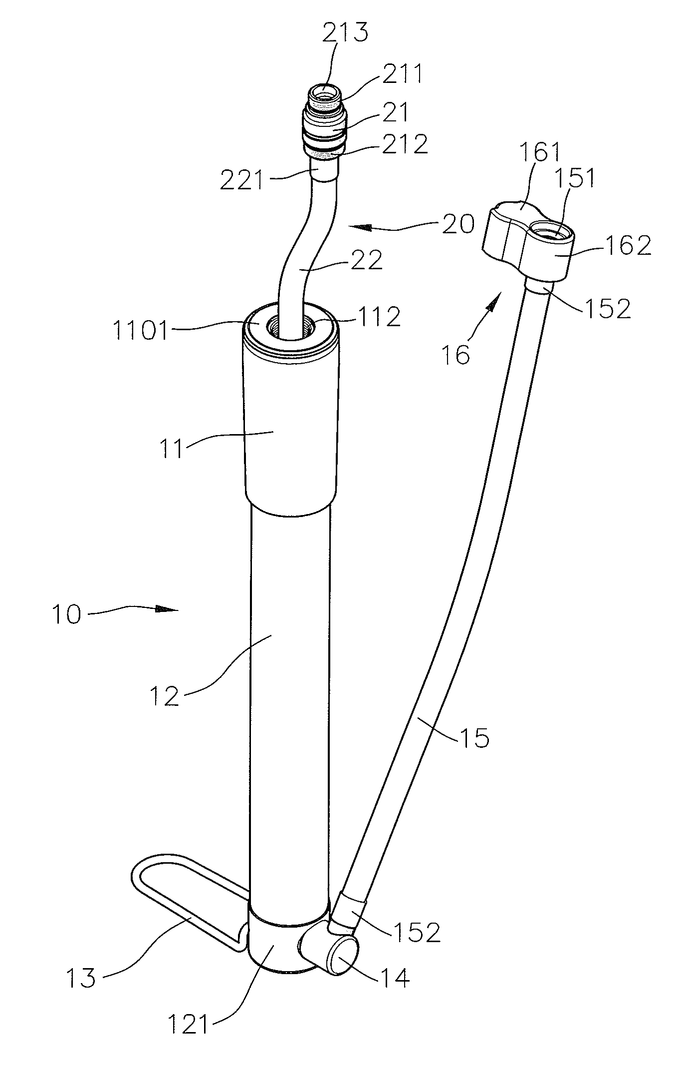
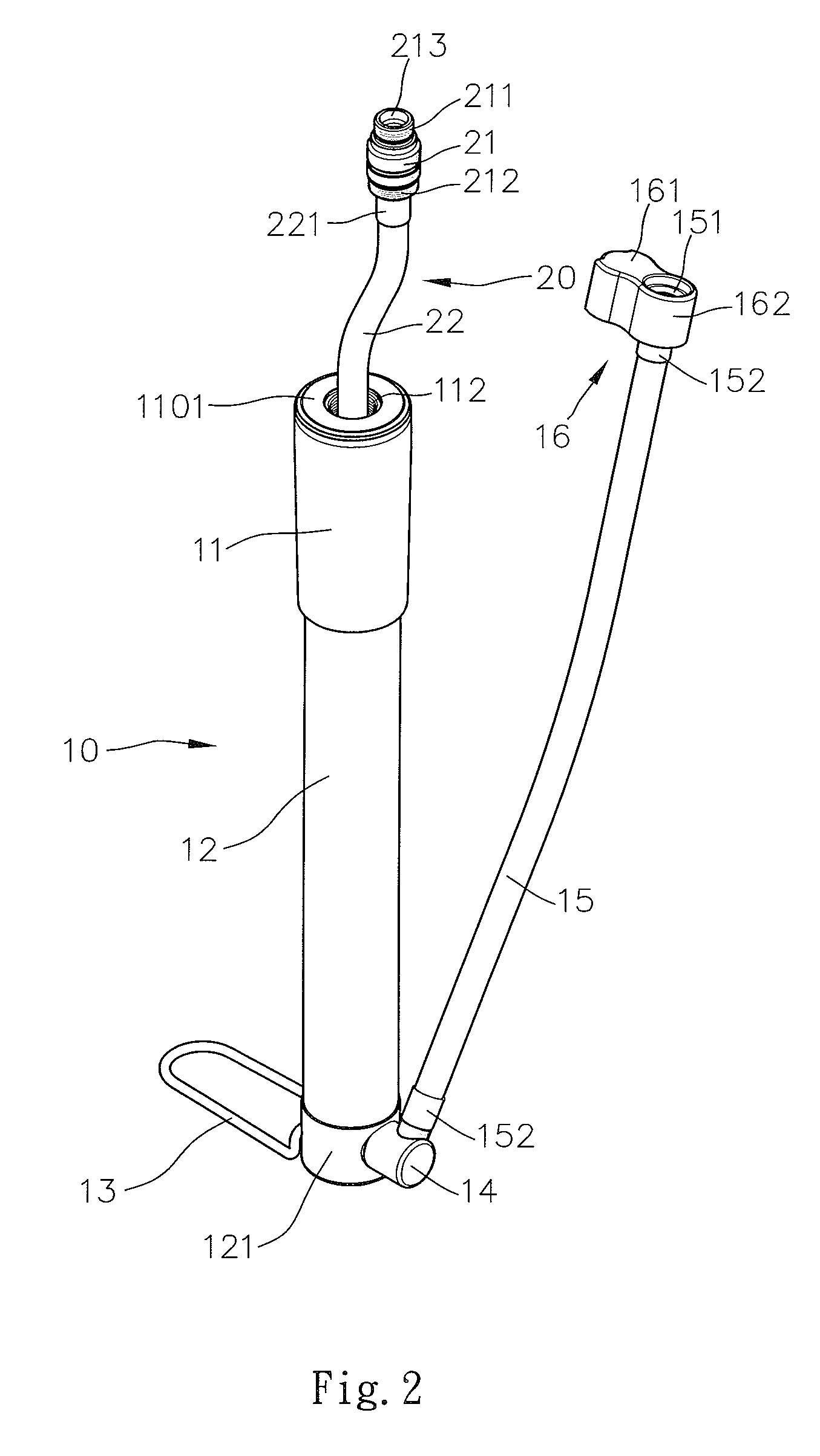
[0015]FIGS. 2-4 show a preferred embodiment of a pump 10 according to the present invention. The pump 10 includes a barrel 12 in the form of a hollow cylinder. A piston rod 111 is slideably received in the barrel 12. A handle 11 is attached to an upper end of the piston rod 111. Compared to conventional mini floor pumps, the piston rod 111 of the present invention includes a hollow receiving portion 1111. In this embodiment, an end portion 1101 in the form of a hollow cylinder is threadedly engaged to the handle 11, and the handle / end portion 1101 is then threadedly engaged with the top end of the piston rod 111. The end portion 1101 includes an inner periphery having a positioning portion 112 with an inner thread. The top end of the piston rod 111 is threadedly engaged with a bottom end of the positioning portion 112. A ring 123 is mounted around the outer periphery of the piston rod 111 at a connection area between the end portion 1101 and the receiving portion 1111. The ring 123 ...


PUM


Abstract

A pump includes a barrel slideably receiving an end of a piston rod. A valve seat is mounted to the barrel and has an air passageway. An adapter is mounted to the valve seat and includes a channel in communication with the air passageway. An end of a hose is connected to the channel. A coupling seat is mounted to the other end of the hose. A connecting block is mounted around the coupling seat. The connecting block is positionable to a side of the barrel. Two rotary inflation nozzles of different specifications are mounted to two ends of another hose. Each rotary inflation nozzle has a coupling thread for engaging with an inner thread of the coupling seat. When not in use, one of the rotary inflation nozzles is inserted into the barrel, and the other rotary inflation nozzle is engaged with an end portion on the piston rod.

Description

BACKGROUND OF THE INVENTION[0001]The present invention relates to a pump and, more particularly, to a floor pump having a reduced volume in a storage state.[0002]Mini portable pumps and floor pumps are two major types of bicycle pumps currently available on the market. Conventional floor pumps have a height approximately to the knees of a user and have a piston rod that can be lifted to a level about a half of a height of an adult. When inflating a tire after engaging a nozzle of a floor pump with a valve of the tire for inflating operation, the user can step on a pedal of the floor pump against the floor and then manually moving the piston rod upward and downward. The air outputted from the cylinder of the floor pump enters the tire to increase the pressure in the tire. Although the floor pump allows stable operation by stepping on the pedal and has a larger size to provide larger air output, the bulky volume of the floor pump requires a larger space for storage and is not easy to ...

Claims


Application Information

Patent Timeline
Patent Type & Authority Applications(United States)
IPC IPC(8): F01B31/00
CPCF04B33/005
Inventor HUANG, YING-CHE
Owner HUANG YING CHE
Features
  • R&D
  • Intellectual Property
  • Life Sciences
  • Materials
  • Tech Scout
  • Unparalleled Data Quality
  • Higher Quality Content
  • 60% Fewer Hallucinations
Learn More