Fuel injection valve

a fuel injection valve and electromagnet technology, applied in the direction of fuel injection apparatus, machine/engine, charge feed system, etc., can solve the problems of high-precision shape, increase in static flow rate and dynamic flow rate, and increase in temperature, ambient pressure, etc., to reduce the clogging of the bubble, simple shape, and easy high-precision work

Inactive Publication Date: 2011-10-20
MITSUBISHI ELECTRIC CORP
View PDF6 Cites 12 Cited by
  • Summary
  • Abstract
  • Description
  • Claims
  • Application Information

AI Technical Summary

Benefits of technology

[0014]Additionally, since vapor and liquid are separated by the swirling flow within the injection hole and bubbles are gathered within the central portion of the injection hole, it is possible to suppress clogging of the bubbles within the injection hole, and to make small changes in flow characteristic (a static flow rate and a dynamic flow rate) accompanying an atmosphere change.
[0015]Additionally, in the present invention, there is no complicated guide passage as shown in JP-A-2003-336563, and the plate convex and the plate concave have simple shapes. Therefore, high-precision working is easy, and it is possible to suppress variation of injection quantity at a low manufacturing cost.

Problems solved by technology

However, since the above fuel injection device of the above JP-A-2003-336563 has an individual guide passage for every injection hole, and is structured such that the flow rectified and accelerated by the guide passage flows into the swirl chamber, there are the following problems.
Therefore, there is a problem in which changes in the flow characteristics (static flow rate and dynamic flow rate) accompanying changes in the temperature, ambient pressure, etc. are increased.
Additionally, since the velocity of flow which flows into the each swirl chamber depends on the shape of the guide passage, there is a problem in that the influence that shape variations of the guide passage has on deviation of injection quantity from each injection hole is great, a high-precision shape is required as the guide passage, and the manufacturing costs increase.
Therefore, there is a possibility that an increase in the amount of exhaust gas or fluctuation of engine rotation by combustion variation is caused.
For this reason, there is a problem in that working of the fuel passage becomes difficult, and in a case where the fuel passage is formed by a press, the lifespan of the die becomes short and the manufacturing costs increase.
Therefore, there is a problem in that working of the fuel passage becomes difficult, and in a case where the fuel passage is formed by a press, the lifespan of the die becomes short and the manufacturing costs increase.

Method used


Image

  • Fuel injection valve
  • Fuel injection valve
  • Fuel injection valve

Examples


embodiment 1

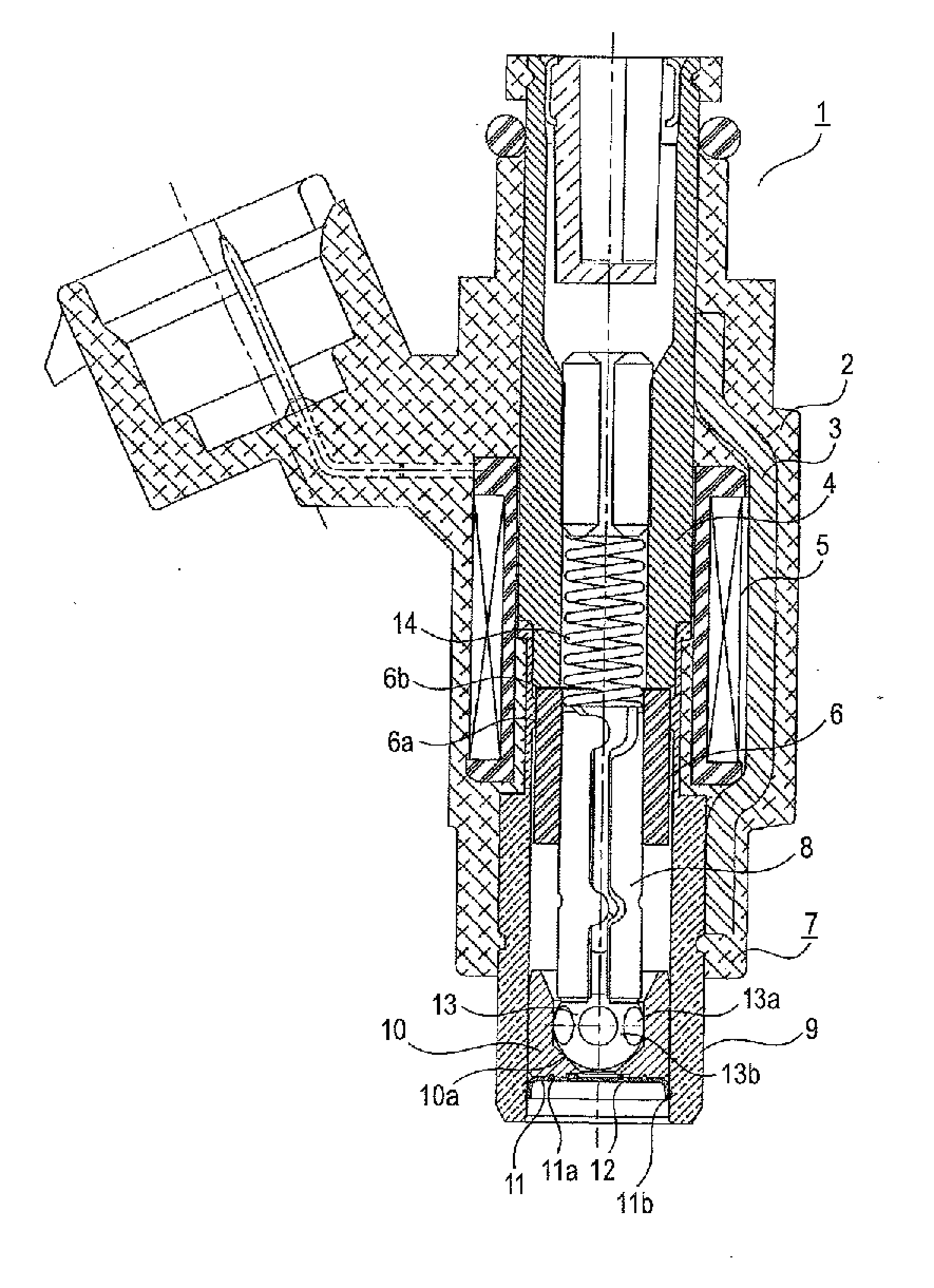
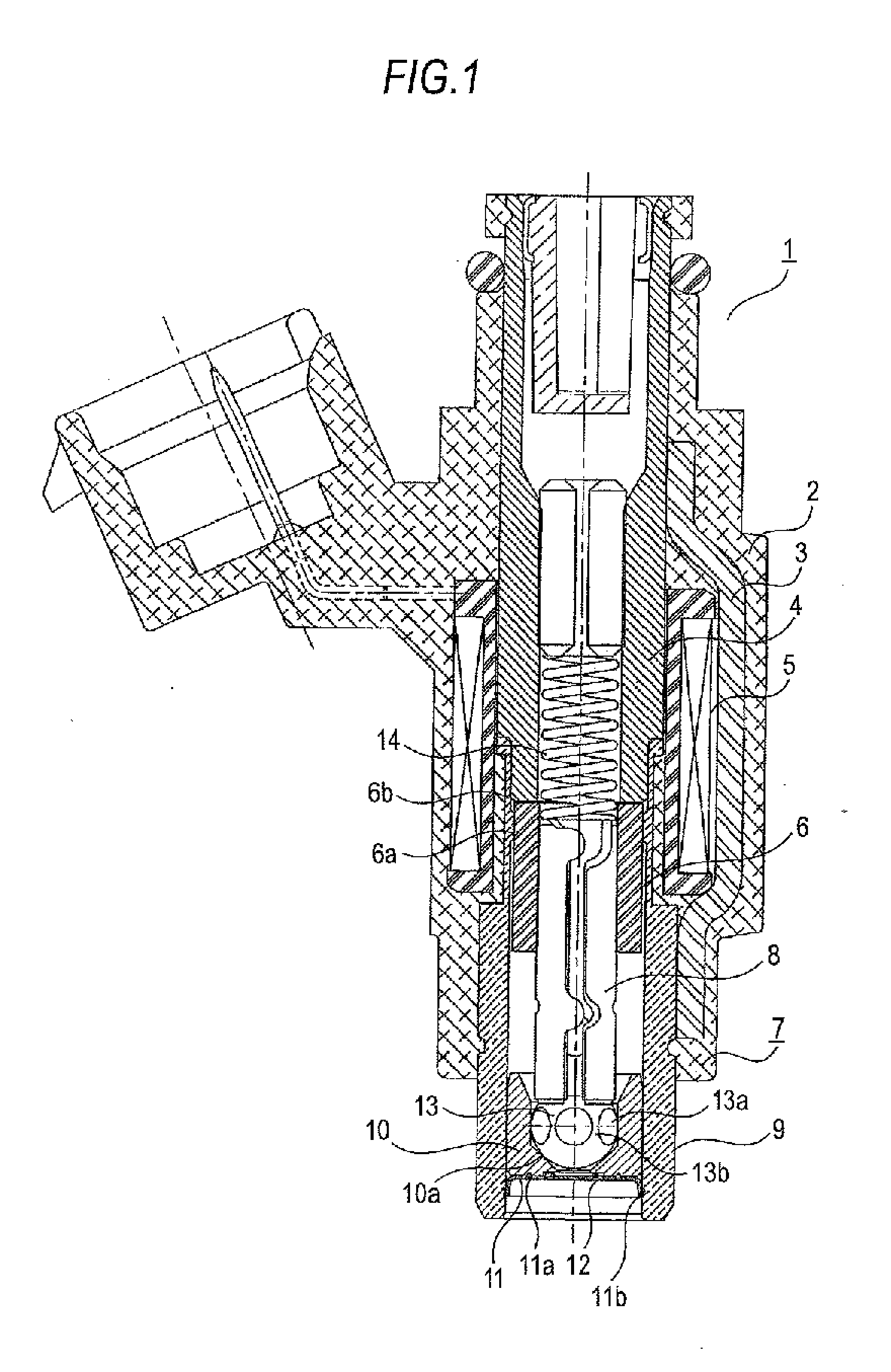
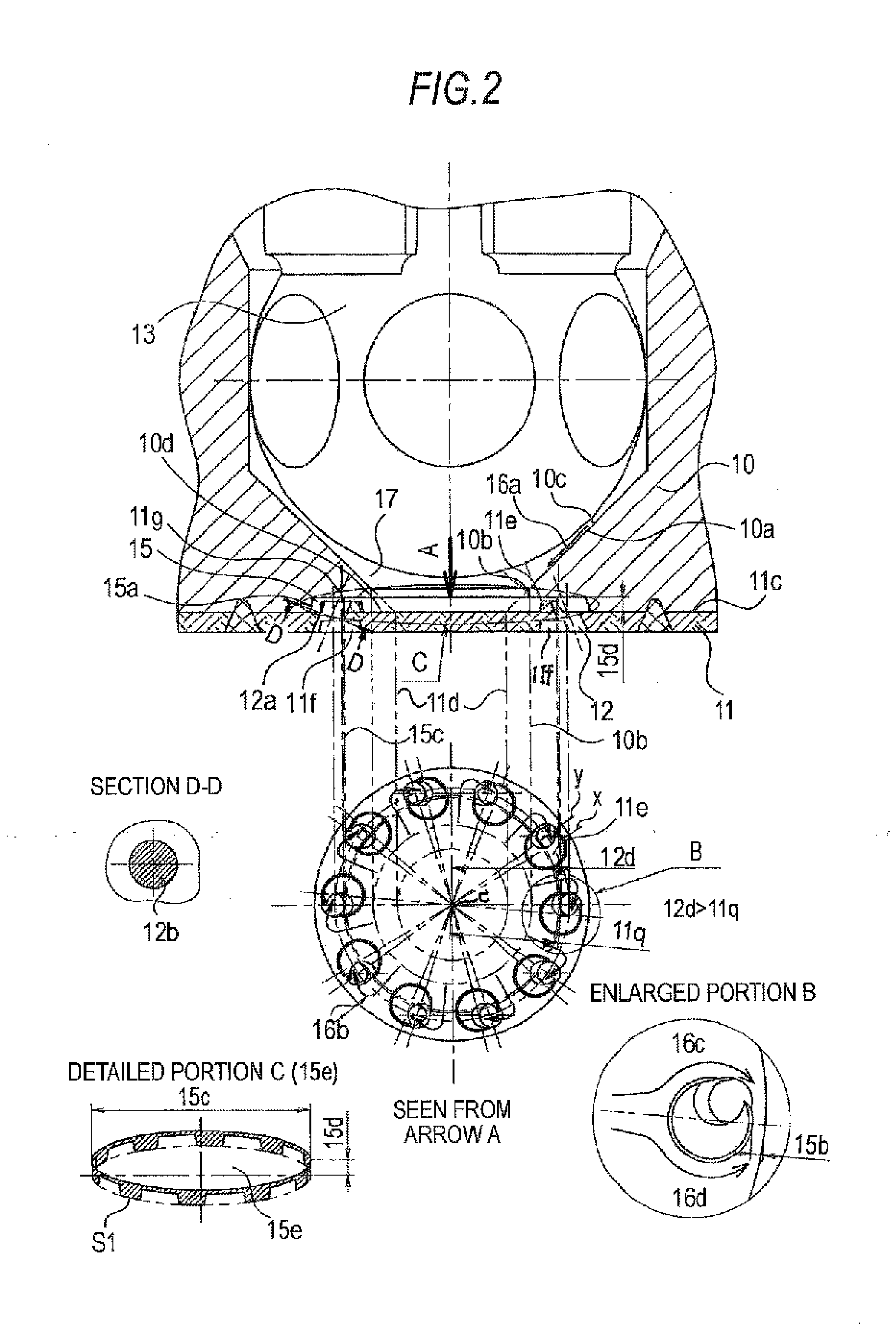
[0028]A sectional view of a fuel injection valve of Embodiment 1 of this invention is shown in FIGS. 1 and 2. In the drawing, reference numeral 1 designates a fuel injection valve, reference numeral 2 designates a solenoid device, reference numeral 3 designates a housing which is a yoke portion of a magnetic circuit, reference numeral 4 designates a core which is a fixed core portion of the magnetic circuit, reference numeral 5 designates a coil, reference numeral 6 designates an armature which is a movable core portion of the magnetic circuit, and reference numeral 7 designates a valve device, and the valve device 7 is constituted by a valve body 8, a main valve body 9, and a valve seat 10. The main valve body 9 is welded after being press-fitted into an external diameter portion of the core 4. The armature 6 is welded after being press-fitted into the valve body 8. The valve seat 10 is inserted into the main valve body 9 in a state where an injection hole plate 11 is combined with...

embodiment 2

[0052]A sectional view of a fuel injection valve of Embodiment 2 is shown in FIG. 5. In the present embodiment, the injection hole plate 11 is arranged so that an extension of the seat surface of the valve seat 10 which is reduced in diameter to the downstream side and the upstream flat surface 11c of the injection hole plate intersect each other to form one imaginary circle 11d, the cavity 15 is not provided in the downstream end surface 10d of the valve seat 10, and the injection holes 12 are formed radially inside the imaginary circle lid in the injection hole plate 11, and the plate convexes 11e are arranged radially inside the imaginary circle 11d.

Additionally, on the upstream flat surface 11c of the injection hole plate 11, the injection hole 12 and the plate convex 11e which straddles the injection hole 12 are arranged so that the distance 11r from the axial center of the fuel injection valve to the center of the plate convex 11e becomes longer than the distance 12e from the...

embodiment 3

[0054]A sectional view of a fuel injection valve of Embodiment 3 is shown in FIG. 6. As shown in the drawing, the fuel injection device is structured so as to reduce each injection hole 12 and the vertical height 11n of the plate convex 11e and reduce the dead volume 17 by providing a flat surface portion 13f, which becomes substantially parallel to the injection hole plate 11, downstream of the sheet portion 13e of the valve body tip portion 13. The other configurations are the same as those of Embodiment 2.

[0055]Thereby, when the valve body is closed, the amount of fuel evaporation under high-temperature negative pressure is low, and changes in flow characteristics (a static flow rate and a dynamic flow rate) accompanying an ambient pressure change can be suppressed. Additionally, when the valve body is opened, the fuel flow 16a which is directed to the radial inside from the axial center of the fuel injection valve from the gap 10c between the valve body tip portion 13 and the va...


PUM


Abstract

A plate convex is formed on the upstream side of the injection hole plate and a plate concave is formed on the downstream side of the injection hole plate so as to form a pair together, a minimum of one set of the plate convexes and the plate concaves are formed, and the injection holes are arranged so that the radial centerline which connects the centerline of the plate convex from the axial center of the fuel injection valve does not overlap the center of the injection hole on an upstream flat surface of the injection hole plate, and the plate convex is arranged so as to straddle the injection hole on the upstream flat surface of the injection hole plate, and the top surface of the plate convex.

Description

BACKGROUND OF THE INVENTION[0001]1. Field of the Invention[0002]The present invention relates mainly to an electromagnetic fuel injection valve to be used for a fuel supply system of an internal combustion engine, and particularly, to the promotion of atomization or suppression of spray shape variations in the spray characteristics of the fuel injection valve, and improvement in the flow rate accuracy in flow rate characteristics or suppression of the amount of change to the ambient pressure change.[0003]2. Description of the Background Art[0004]In recent years, while regulation of the exhaust gases of an automobile or the like has tightened, improvement in the atomization of fuel spray injected from the fuel injection valve is required. With respect to the atomization of the fuel spray, various kinds of deliberation have already been made up to this point.[0005]For example, a fuel injection device (see JP-A-2003-336563) is suggested in which an individual guide passage is provided ...

Claims


Application Information

Patent Timeline
Patent Type & Authority Applications(United States)
IPC IPC(8): F02M61/00
CPCF02M61/1853
Inventor SAKATA, YUKITAKAHASHII, NAOYAMUNEZANE, TSUYOSHI
Owner MITSUBISHI ELECTRIC CORP
Why Eureka
Try Eureka