
Foldable rotor blade for toy helicopter

a toy helicopter and propeller blade technology, applied in the field of toy helicopters, can solve the problems of crushing the toy helicopter, destroying the balance, and inexperienced beginners may have a hard time controlling the toy helicopter toward the desired direction, so as to achieve more stably control the helicopter, provide an upward force, and lift up the body

Inactive Publication Date: 2011-10-20
CHENG RANDY
View PDF2 Cites 7 Cited by
  • Summary
  • Abstract
  • Description
  • Claims
  • Application Information

AI Technical Summary

Benefits of technology

"The invention is a foldable propeller blade for toy helicopters that can absorb external impact force to reduce damage. The blade can automatically align itself to regain control and balance after an impact. The blade is designed with U-shaped hinge joints that prevent the blade leafs from bumping together. The foldable blade is coaxially coupled with the rotor shaft and auxiliary shaft to provide more stable control of the helicopter. The technical effects of the invention are improved safety and stability of toy helicopters."

Problems solved by technology

The common problem for the beginners to control the remotely controlled helicopter is the highly possibility of crushing the toy helicopter due to the unwanted movements, such as lateral movement, to destroy the balance of the toy helicopter flying in the air.
Moreover, the inexperienced beginners may have a hard time to controllably steer the toy helicopter toward the desired directions.
Therefore, the propeller blade, having a larger rotational radius with respect to the helicopter body itself, tends to easily hit an object, so that the entire propeller blade fixedly mounted at the rotor shaft may be broken, deformed, destroyed, or tilted, so as to lose the gravity of the helicopter in the air to accidentally drop off the helicopter.

Method used


Image

  • Foldable rotor blade for toy helicopter
  • Foldable rotor blade for toy helicopter
  • Foldable rotor blade for toy helicopter

Examples


Embodiment Construction

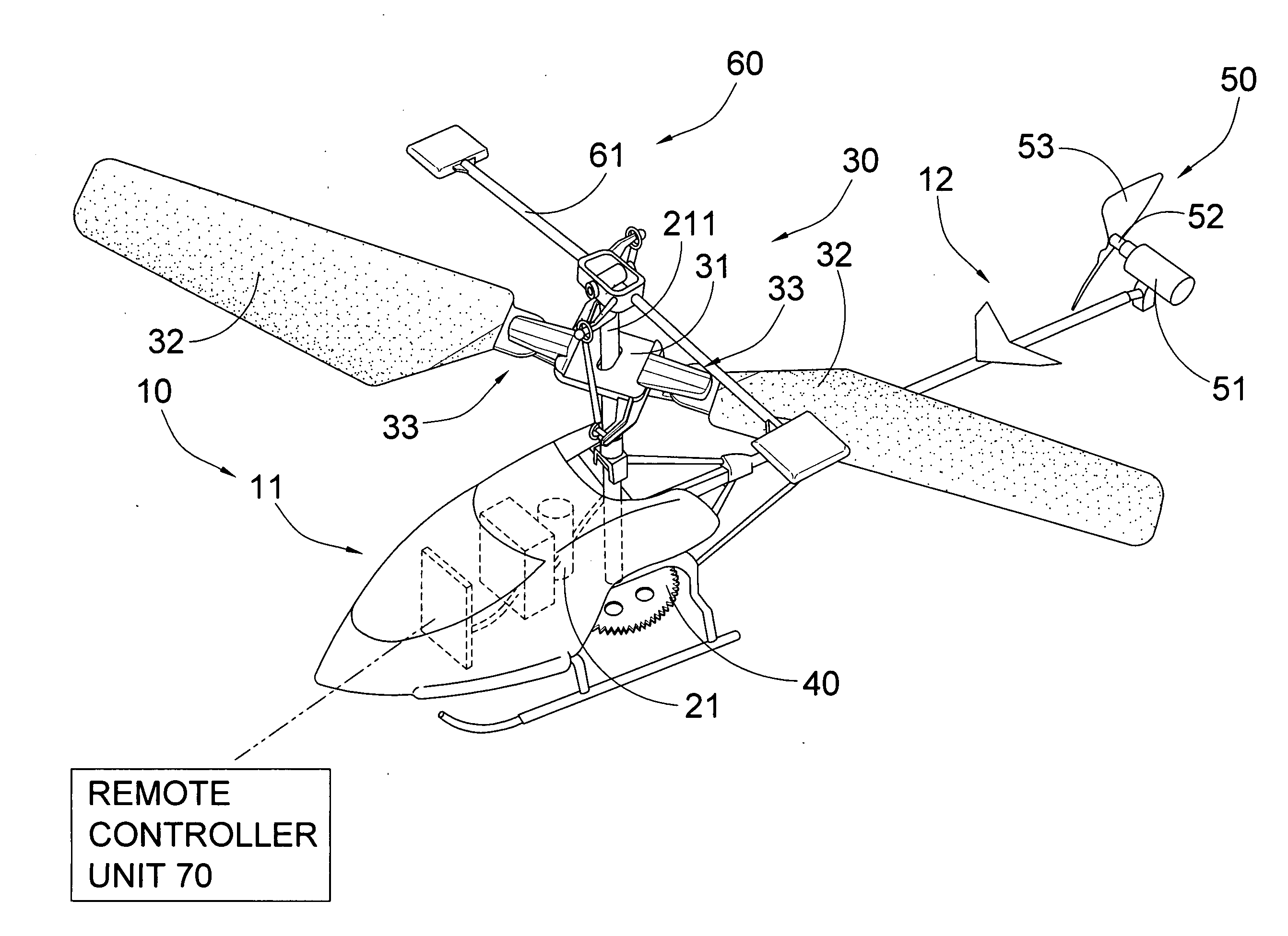
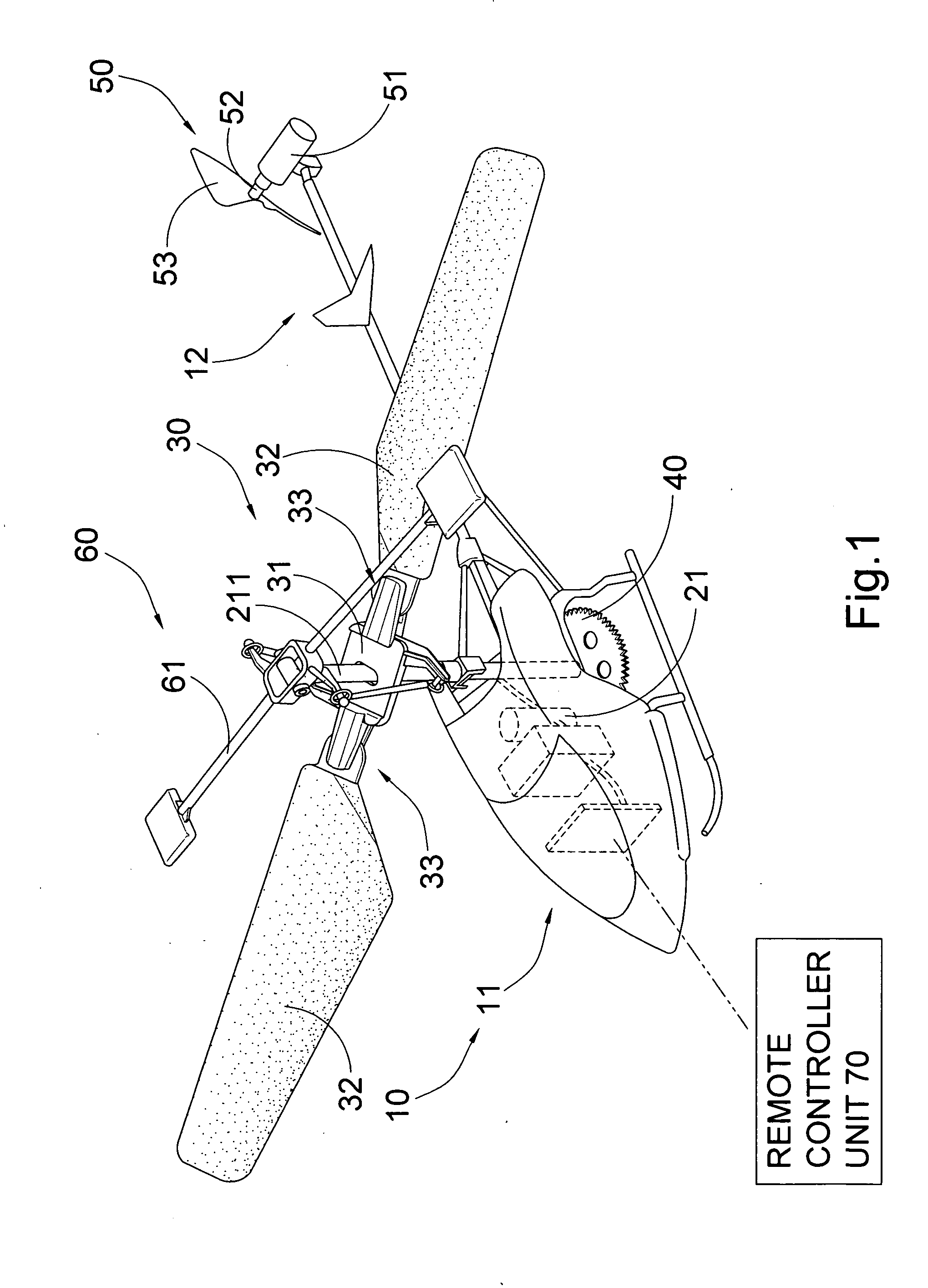
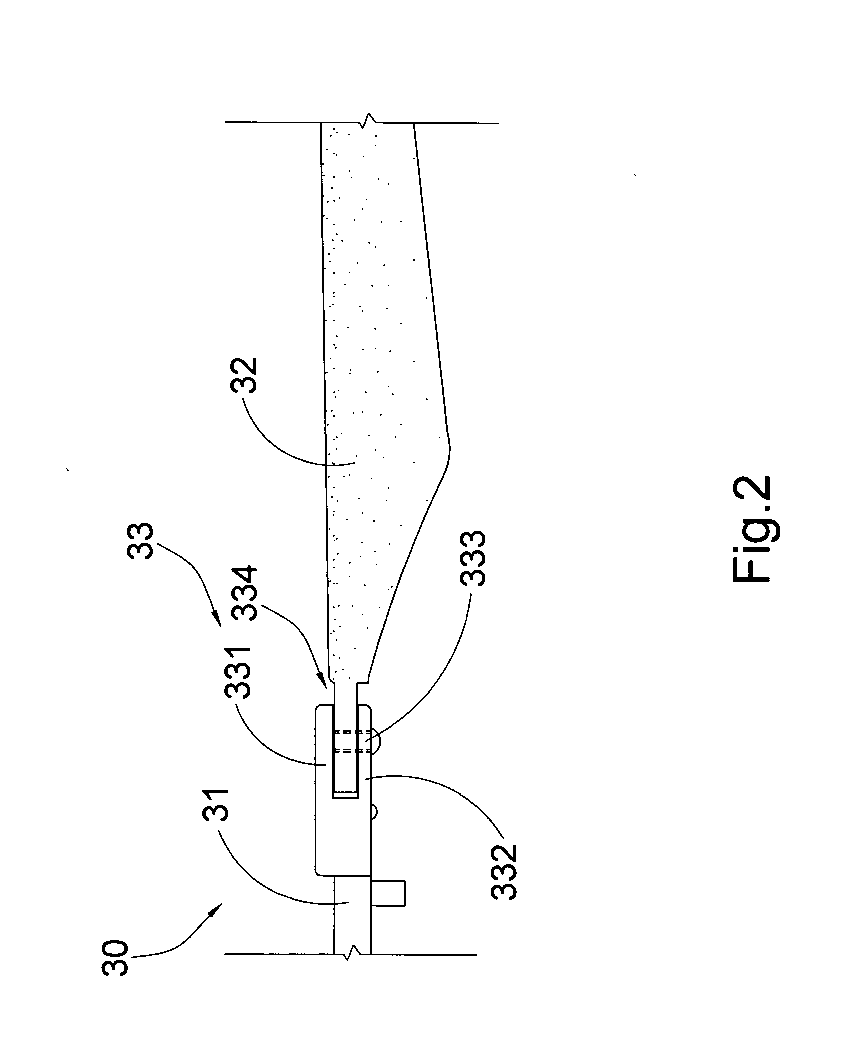
[0023]Referring to FIGS. 1 to 3 of the drawings, a toy helicopter according to the preferred embodiment of the present invention, wherein the toy helicopter has a body 10 and a rotor arrangement 20 which comprises a power rotor 21 accommodated within the body 10.

[0024]As shown in FIG. 1, the body 10 has a body portion 11 having a housing for accommodating the power rotor 21 therewithin, and a tail portion 12 rearwardly extended from the body portion 11. The power rotor 21 is mechanically engaging with the power rotor shaft 211 such that when the power rotor 21 is activated, the power rotor shaft 211 is driven to rotate for generating a rotational power.

[0025]The toy helicopter also comprises a foldable propeller blade 30 coaxially mounted at the power rotor shaft 211, in such a manner that the propeller blade 30 is driven to create a rotational motion for mainly and evenly providing an upward force as a lift force to lift up the body 10 of the toy helicopter, so as to keep the toy h...


PUM


Abstract

A toy helicopter includes a body, a rotor arrangement for generating a rotational power, and a foldable propeller blade including a bracket member coaxially mounted to the rotor arrangement and at least two blade leafs pivotally and symmetrically coupling with the bracket member in a horizontally movable manner to generate an evenly rotational motion thereof, so as to stably provide an upward force to lift up said body. When one of the blade leafs is pivotally folded by an external force to misalign the blade leafs with each other, the bracket member is kept rotating to generate a centrifugal force to essentially re-situate the blade leafs in line with each other so as to re-gain a control and balance of the body.

Description

BACKGROUND OF THE PRESENT INVENTION[0001]1. Field of Invention[0002]The present invention is related to a toy helicopter, and more particularly, but not exclusively, to a structure of propeller blade of a toy helicopter adapted for being folded when an external force is applied thereat and for being unfolded by itself during operation.[0003]2. Description of Related Arts[0004]The toy helicopter normally has a driven rotor for driving a rotor shaft to move in a rotational manner, and a propeller blade arrangement coaxially coupling with the rotor shaft for being driven to generate a rotational movement, in such a manner that the propeller blade generates an opposite trust force to upwardly lift up the toy helicopter. The propeller blade arrangement may also be arranged to be controllably driven to adjust the steering direction of the toy helicopter. Therefore, the toy helicopter is able to take off and land in a vertical manner via the propeller blade to increase the mobility and fle...

Claims


Application Information

Patent Timeline
Patent Type & Authority Applications(United States)
IPC IPC(8): B64C27/54B64C27/50B64C27/82
CPCA63H27/12
Inventor CHENG, RANDY
Owner CHENG RANDY
Learn More