
Charged particle beam writing apparatus and charged particle beam writing method

Active Publication Date: 2011-10-20
NUFLARE TECH INC
View PDF2 Cites 19 Cited by
  • Summary
  • Abstract
  • Description
  • Claims
  • Application Information

AI Technical Summary

Benefits of technology

[0011]In accordance with one aspect of the present invention, a beam writing apparatus includes a selection unit configured to select a dose equation from a plurality of dose equations for calculating a dose of a beam, for each small region of a plurality of small regions made by virtually dividing a writing region of a target workpiece into mesh-like regions, a dose calculation unit configured to calculate a dose of a beam which is shot into a small region of the plurality of small regions, by using a selected dose equation, for the each small region, and a writing unit configured to write a desired pattern in the small region, by using a calculated dose, for the each small region.
[0012]In accordance with one aspect of the present invention, a beam writing method includes selecting a dose equation from a plurality of dose equations for calculating a dose of a beam, for each small region of a plurality of small regions made by virtually dividing a writing region of a target workpiece into me

Problems solved by technology

In the meantime, with recent miniaturization of patterns, writing time of the writing apparatus becomes long, and thus, shortening of the time is required.
However, in order to write a pattern in accordance with sizes, it is necessary to make a calculated dose incident on a resist, and thus, the conventional method has a limit of reducing the writing time.
Thus, as has been mentioned, an excessive dose exists depending on a figure or its irradiation position, and accordingly, there is a problem of taking a writing time longer than needed because of such excessive dose.

Method used


Image

  • Charged particle beam writing apparatus and charged particle beam writing method
  • Charged particle beam writing apparatus and charged particle beam writing method
  • Charged particle beam writing apparatus and charged particle beam writing method

Examples


embodiment 1

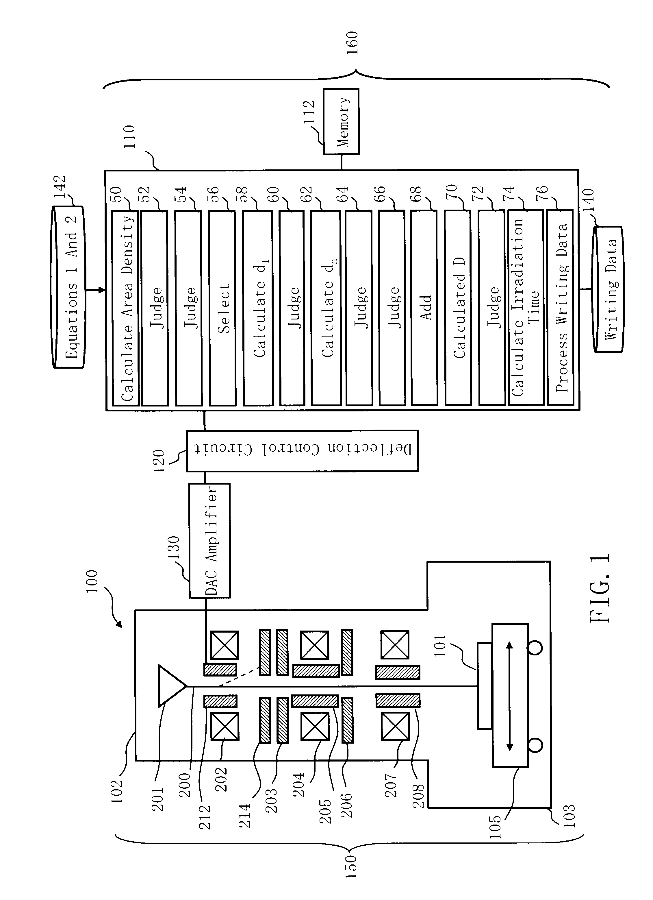
[0031]FIG. 1 is a schematic diagram showing a structure of a writing apparatus according to Embodiment 1. In FIG. 1, a writing apparatus 100 includes a writing unit 150 and a control unit 160. The writing apparatus 100 is an example of a charged particle beam writing apparatus, and especially, an example of a variable-shaped electron beam (VSB) writing apparatus. The writing unit 150 includes an electron lens barrel 102 and a writing chamber 103. In the electron lens barrel 102, there are arranged an electron gun assembly 201, an illumination lens 202, a blanking deflector (blanker) 212, a blanking aperture 214, a first shaping aperture 203, a projection lens 204, a deflector 205, a second shaping aperture 206, an objective lens 207, and a deflector 208. In the writing chamber 103, there is arranged an XY stage 105 which is movable at least in the XY direction. On the XY stage 105, a target workpiece 101 serving as a writing target is placed. The target workpiece 101 is, for example...

embodiment 2

[0065]Although, in Embodiment 1, the condition (first condition) that the pattern area density ρ(i,j) of the mesh region (i,j) concerned is 100% and each of the pattern area densities of the eight mesh regions which adjacently surround the mesh region (i,j) concerned is 100% is used as a condition of selecting the dose equation 2, it is not limited thereto. In Embodiment 2, other selection conditions will be described.

[0066]FIG. 6 is a schematic diagram showing a structure of the writing apparatus according to Embodiment 2. Except for adding a bilinear area distribution value calculation unit 78 in the control computer 110, FIG. 6 is the same as FIG. 1.

[0067]FIG. 7 is a flowchart showing main steps of a writing method according to Embodiment 2. FIG. 7 is the same as FIG. 3 except for adding the judgment step (S108) instead of the judgment step (S106), adding a bilinear area distribution value calculation step (S104) between the area density calculation step (S102) and the judgment s...

embodiment 3

[0079]In Embodiments 1 and 2, the case of writing using a charged particle beam has been explained. However, the method of selecting and using a dose equation described above is not limited to be applied to the case of a charged particle beam. It is also preferable to be applied to the case of a light beam (laser beam). In the following, the description is the same as Embodiment 1 except for the contents specially explained.

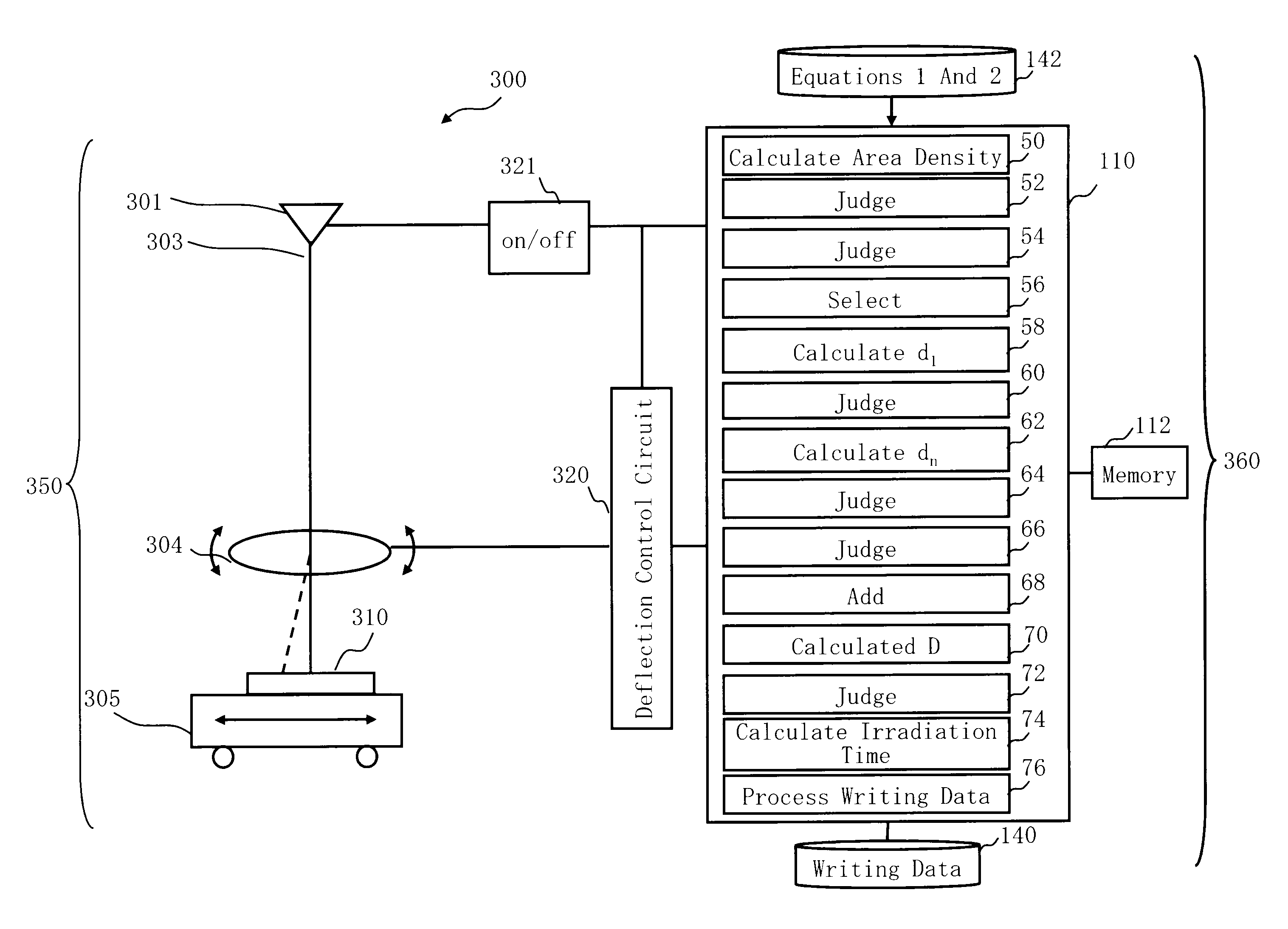
[0080]FIG. 11 shows a schematic diagram of a structure of the writing apparatus according to Embodiment 3. In FIG. 11, the writing apparatus 300 is an example of a laser beam writing apparatus. The writing apparatus 300 includes a writing unit 350 and a control unit 360. The writing unit 350 includes a light source 301, a lens 304, and a stage 305. The control unit 360 includes a control computer 110, a memory 112, a deflection control circuit 320, a switch circuit 321, and memories 140 and 142, such as a magnetic disk. The internal structure of the control compu...


PUM


Abstract

A beam writing apparatus according to an embodiment includes a selection unit configured to select a dose equation from a plurality of dose equations for calculating a dose of a beam, for each small region of a plurality of small regions made by virtually dividing a writing region of a target workpiece into mesh-like regions, a dose calculation unit configured to calculate a dose of a beam which is shot into a small region of the plurality of small regions, by using a selected dose equation, for the each small region, and a writing unit configured to write a desired pattern in the small region, by using a calculated dose, for the each small region.

Description

CROSS-REFERENCE TO RELATED APPLICATION[0001]This application is based upon and claims the benefit of priority from prior Japanese Patent Application No. 2010-097295 filed on Apr. 20, 2010 in Japan, the entire contents of which are incorporated herein by reference.BACKGROUND OF THE INVENTION[0002]1. Field of the Invention[0003]Embodiments of the present invention relate to a charged particle beam writing apparatus and a charged particle beam writing method. For example, they relate to a method for obtaining a dose of electron beam radiation in the electron beam writing.[0004]2. Related Art[0005]The microlithography technique which advances microminiaturization of semiconductor devices is extremely important as being a unique process whereby patterns are formed in the semiconductor manufacturing. In recent years, with high integration of LSI, the line width (critical dimension) required for semiconductor device circuits is decreasing year by year. In order to form a desired circuit pa...

Claims


Application Information

Patent Timeline
IPC IPC(8): G21K5/10G03F1/54H01L21/027
CPCB82Y10/00H01J37/3174H01J37/3026B82Y40/00
Inventor MATSUMOTO, HIRONOBU
Owner NUFLARE TECH INC
Learn More