

LED driving device, light source device, and liquid crystal displaying device
a technology of driving device and liquid crystal display device, which is applied in the direction of lighting apparatus, light sources, electroluminescent light sources, etc., can solve the problem of 104/b> maximum power dissipation of constant current transistor
- Summary
- Abstract
- Description
- Claims
- Application Information
AI Technical Summary
Benefits of technology
Problems solved by technology
Method used
Image

Examples
first embodiment
Advantages of First Embodiment
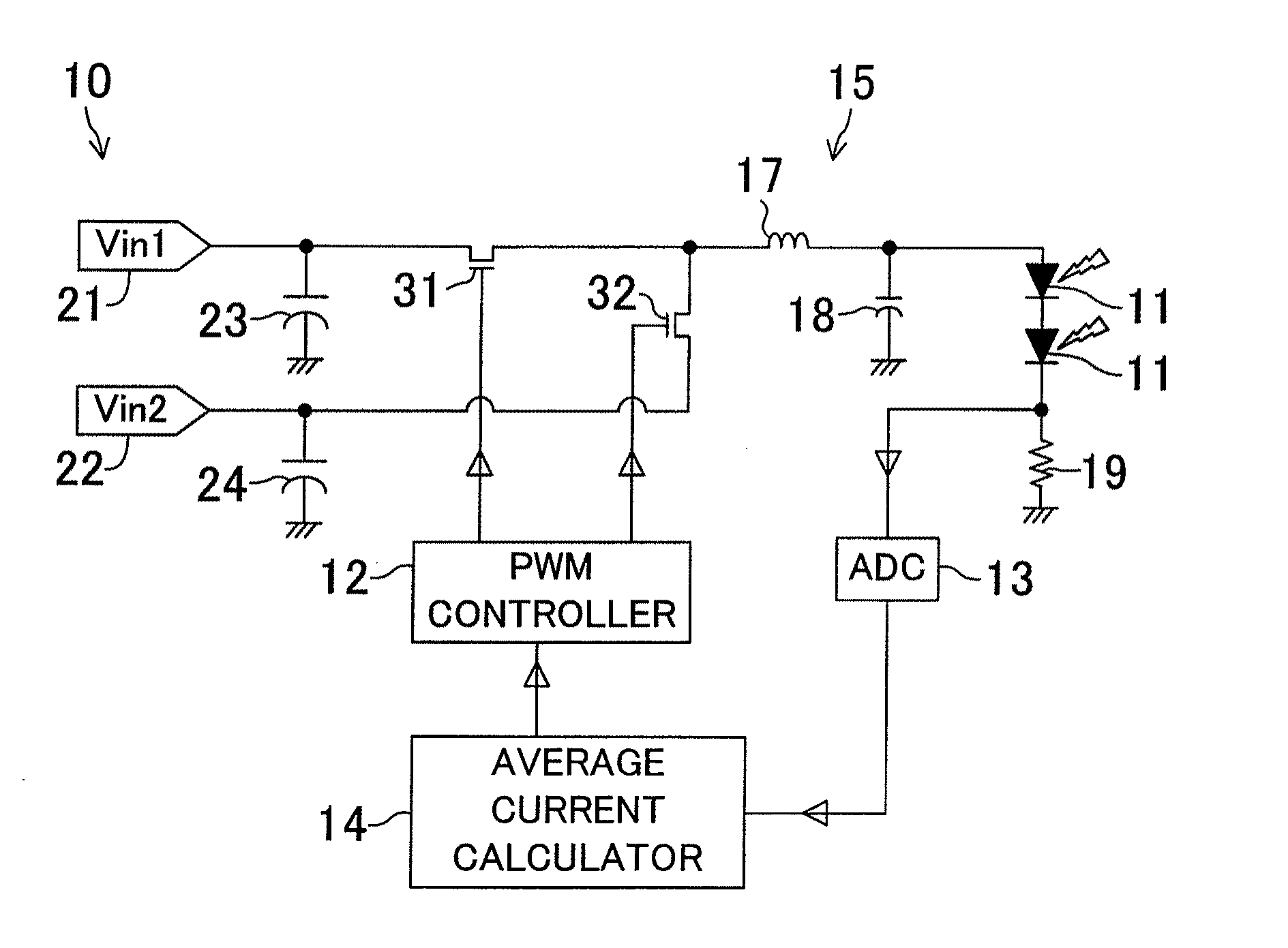
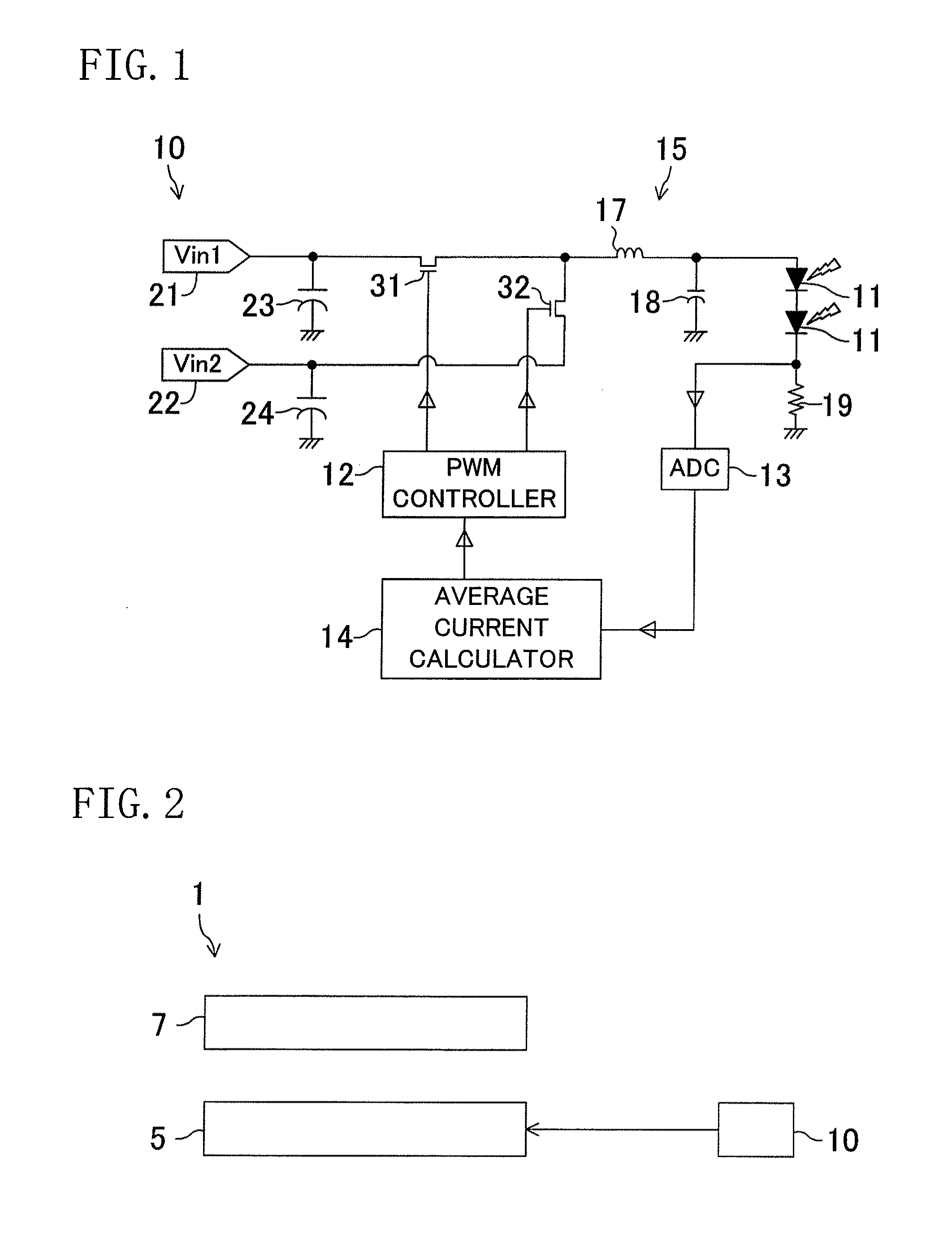
[0100]As described above, in this embodiment, the upper and lower limit values of each of the first power supply voltage Vin1 input to the first input section 21 and the second power supply voltage Vin2 input to the second input section 22 are defined as indicated by Expression (1). Moreover, the PWM controller 12 alternately connects the first input section 21 or the second input section 22 to the LEDs 11. In addition, the ratio of the connection time period between the first input section 21 and the LEDs 11 to the connection time period between the second input section 22 and the LEDs 11 is controlled, based on the average forward current detected by the AD converter 13 and the target value of the average forward current, so that the value of the average forward current approaches the target value.
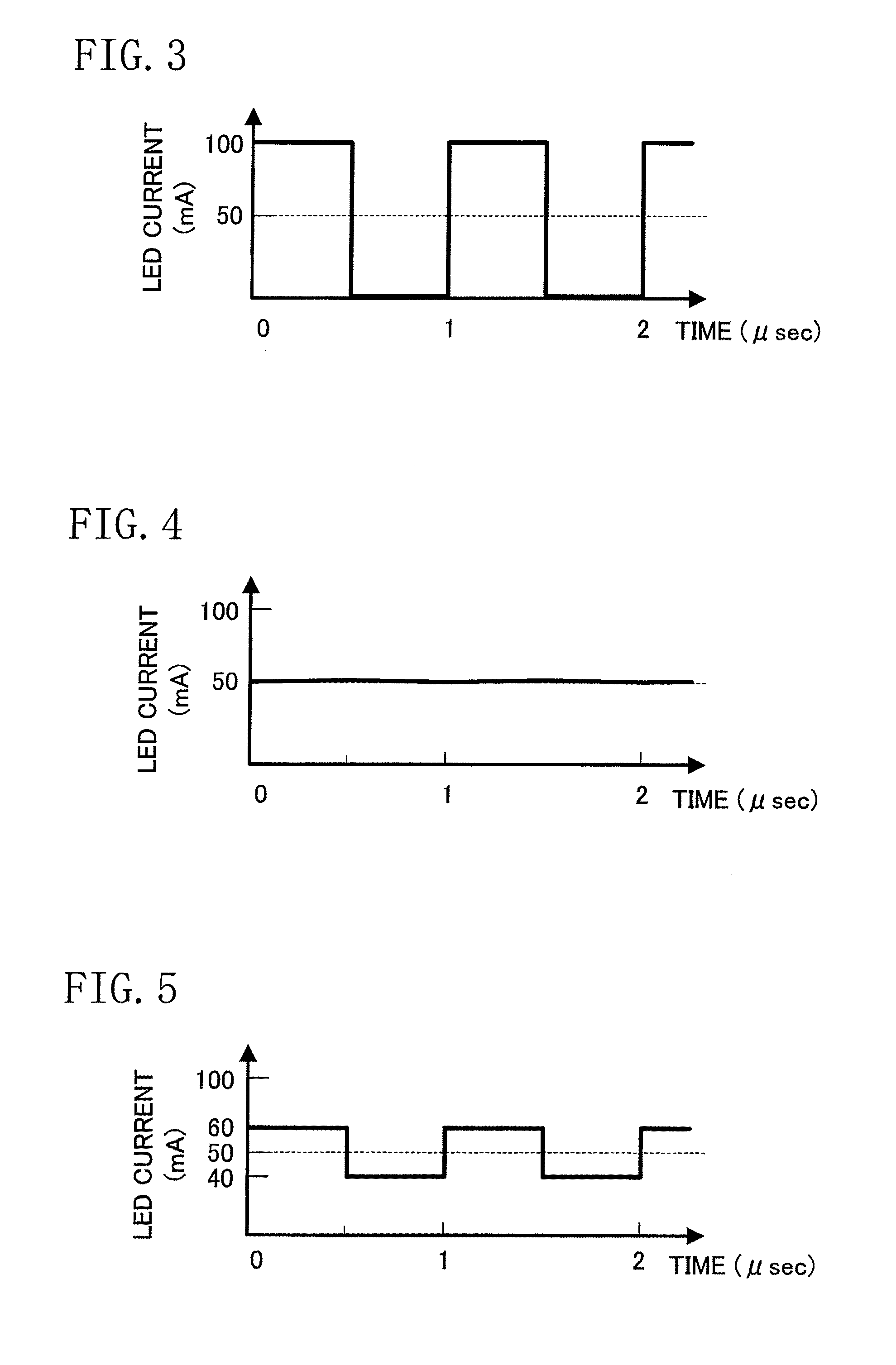
[0101]Therefore, the amplitude of the current waveform of the current supplied to the LEDs 11 can be caused to be relatively small, and the average forward ...
second embodiment
Advantages of Second Embodiment
[0110]Therefore, according to the second embodiment, not only advantages similar to those of the first embodiment are obtained, but also the LEDs 11 can be switched on / off independently from the current control performed by the average current calculator 14 and the PWM controller 12. Moreover, a PWM dimming control of the LEDs 11 can be performed.
Third Embodiment of the Invention
[0111]FIG. 12 shows a third embodiment of the present invention.
[0112]FIG. 12 is a circuit diagram showing a circuit configuration of an LED drive device according to the third embodiment.
[0113]The third embodiment is similar to the first embodiment, except that the LED switching controller 25 for switching on / off the LEDs 11 is connected to the PWM controller 12.
[0114]The LED switching controller 25 controls the PWM controller 12 so that the PWM controller 12 switches between a first state in which neither the first input section 21 nor the second input section 22 is electrica...
third embodiment
Advantages of Third Embodiment
[0117]Therefore, according to the third embodiment, not only advantages similar to those of the first embodiment are obtained, but also an additional switching section (the third transistor 33) is not required to switch on / off the LEDs 11. Moreover, a PWM dimming control of the LEDs 11 can be performed.
Fourth Embodiment of the Invention
[0118]FIGS. 13 and 14 show a fourth embodiment according to the present invention.
[0119]FIG. 13 is a circuit diagram showing a circuit configuration of an LED drive device according to the fourth embodiment. FIG. 14 is a graph showing a current waveform in the LED drive device of the fourth embodiment.
[0120]Although, in the above embodiments, the LED drive circuit 10 includes a single circuit unit 20, the present invention is not limited to this. Alternatively, the LED drive circuit 10 may include a plurality of circuit units 20.
[0121]Each circuit unit 20 includes a plurality of LEDs 11, a first input section 21, a second...
PUM
 Abstract
Description
Claims
Application Information