Insert type antenna module for portable terminal and method for manufacturing the same

a portable terminal and antenna module technology, applied in the direction of independent non-interaction antenna combinations, protective material radiating elements, other domestic articles, etc., can solve the problems of low signal reception, large volume, high defect rate of products, etc., to reduce weight, volume and area, the thickness of the antenna module is uniform, and the terminal is compact. the effect of siz

Inactive Publication Date: 2011-10-20
MA SANG YONG
View PDF5 Cites 21 Cited by
  • Summary
  • Abstract
  • Description
  • Claims
  • Application Information

AI Technical Summary

Benefits of technology

[0011]In a manufacture of an antenna module for a portable terminal according to the present invention, a cover is injection-molded at one exposed side of an antenna core in a state that an antenna core to which an antenna radiation member is engaged is inserted, so a thickness of an antenna module is uniform, and a weight, volume and area decrease, which leads to a lightness and a compact size of a terminal housing. A plurality of antenna radiation parts can be integrated in

Problems solved by technology

The conventional antenna module is installed at an outer side of a terminal, which leads to a huge volume problem.
The above patent, however, has a lot of problems: a PCB pattern is transformed, housing has a limit in making it smaller and thinner, a curve with at least two axes is impossible to form, which leads to a low signal reception and a high defects in products, a manuf

Method used


Image

  • Insert type antenna module for portable terminal and method for manufacturing the same
  • Insert type antenna module for portable terminal and method for manufacturing the same
  • Insert type antenna module for portable terminal and method for manufacturing the same

Examples


Embodiment Construction

Modes for Carrying Out the Invention

[0037]The preferred embodiments of the present invention will be described with reference to the accompanying drawings.

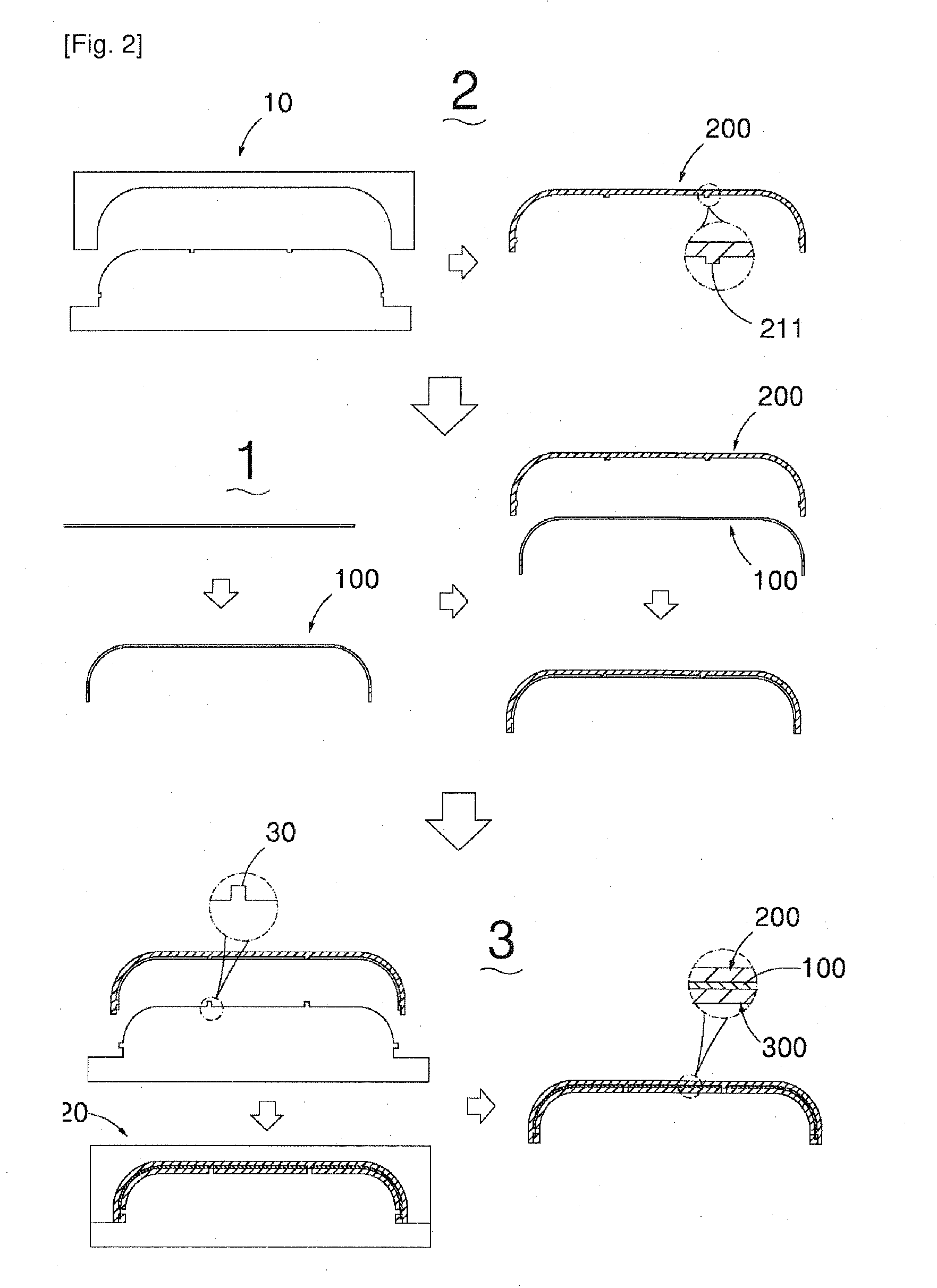
[0038]The present invention is directed to forming, in a way of insert-injection, an antenna core to which an antenna radiation part is engaged and manufacturing a cover in a way of insert-injection molding, thus improving a productivity and durability.

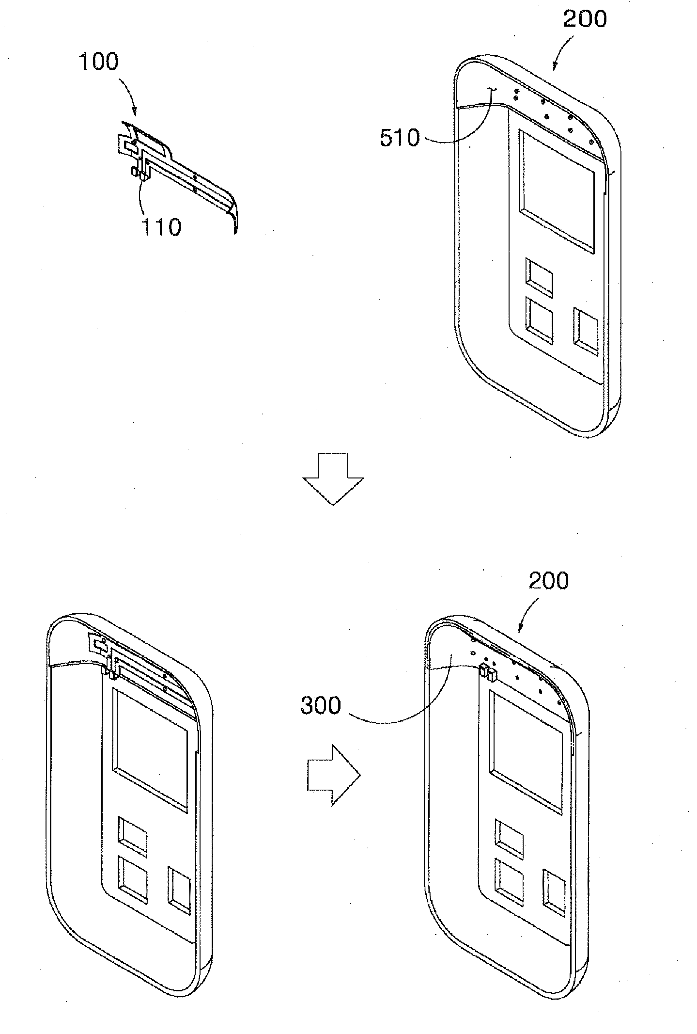
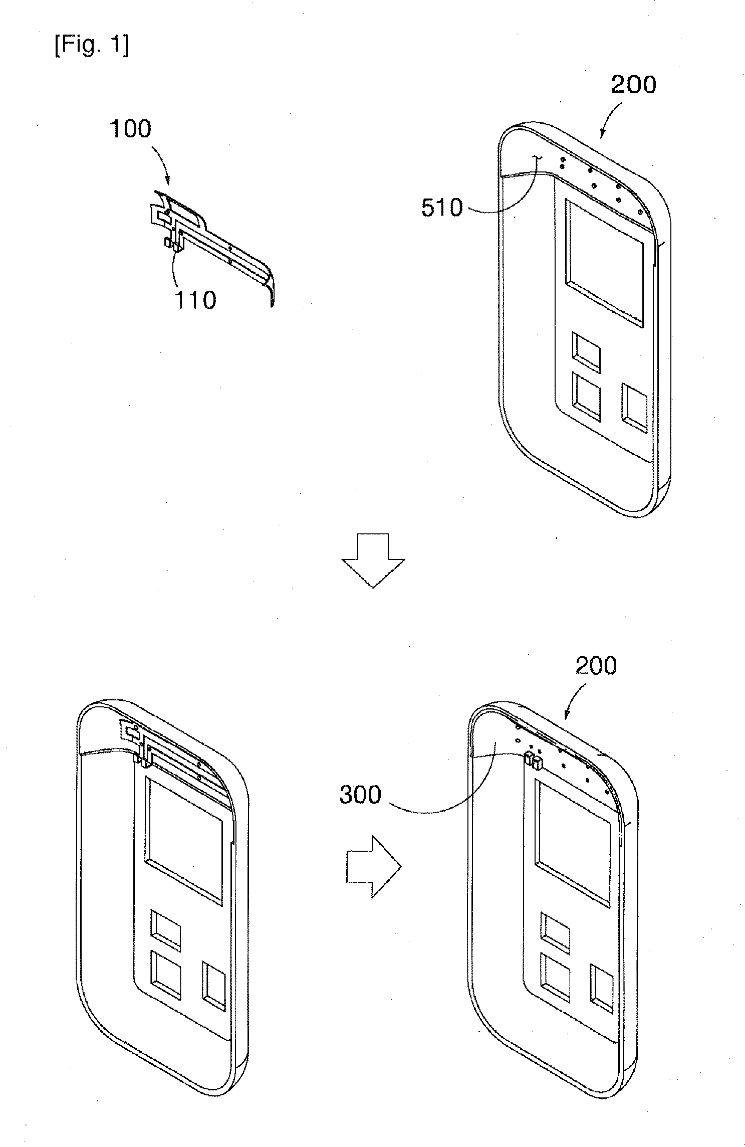
[0039]In a manufacture of an antenna module for a portable terminal according to the present invention, as shown in FIGS. 1 to 7, the method for manufacturing an insert type antenna module for a portable terminal comprises an antenna radiation part manufacture step 1 in which an antenna radiation part 100 is manufactured by cutting and bending a conductive metal sheet for an antenna radiation part to have a plane and a curve with at least one axis; an antenna core manufacture step 2 in which an antenna core 200 is manufactured, which antenna core is engaged by one among an adhering ...


PUM

PropertyMeasurementUnit
Thicknessaaaaaaaaaa
Lengthaaaaaaaaaa
Weightaaaaaaaaaa

Abstract

An insert type antenna module for a portable terminal and a method for manufacturing the same are disclosed, which make it possible to come up with an easier manufacture of an antenna module and to enhance the durability of an antenna module. The antenna radiation part is formed of a conductive metal sheet having a curve with at least one axis, and the antenna code to which the antenna radiation part is engaged is inject-formed, and a cover is inject-formed at one exposed outer surface of the antenna core in a state that the antenna core is inserted. The present invention is characterized in that in a manufacture of an antenna module for a mobile terminal, a cover is inject-formed at an outer surface of the exposed side of an antenna core in a state that an antenna core to which an antenna radiation part is engaged is inserted, which results in manufacturing a uniform thickness of an antenna module and decreasing a weight, volume and area, thus achieving a lighter and thinner terminal housing. Since a plurality of radiation parts can be integrated in one housing, a manufacture process can be more simplified as compared to a conventional antenna manufacture method (each antenna is manufactured and attached), thus obtaining an excellent quality and cost-effective product in a terminal housing manufacture process.

Description

CLAIM OF PRIORITY[0001]This application makes reference to, incorporates the same herein, and claims all benefits accruing under 35 U.S.C. § 119 from applications filed in the Korean Intellectual Property Office on 11 Dec. 2008 and there duly assigned Ser. No. 10-2008-0125877, on 31 Mar. 2009 and there duly assigned Ser. No. 10-2009-0027587, on 13 Jul. 2009 and there duly assigned Ser. No. 10-2009-0063476, and on 2 Sep. 2009 and there duly assigned Ser. No. 10-2009-0082243. Furthermore, this application makes reference to, incorporates the same herein, and claims all benefits accruing under 35 U.S.C. § 365(c) of my PCT International application entitled ANTENNA MODULE FOR PORTABLE TERMINAL HAVING ANTENNA INSERTED THEREIN AND MANUFACTURING PROCESS OF THE ANTENNA MODULE filed on 11 Dec. 2009 and duly assigned Serial No. PCT / KR2009 / 007454.BACKGROUND OF THE INVENTIONTechnical Field[0002]The present invention relates to an insert type antenna module for a portable terminal and a method f...

Claims


Application Information

Patent Timeline
IPC IPC(8): H01Q1/24H01P11/00
CPCB29C45/1671H01Q21/28B29K2995/0005B29L2031/3456Y10T29/49016H01Q1/243B29L2031/3437H01Q1/40
Inventor MA, SANG-YONG
Owner MA SANG YONG
Why Eureka
Try Eureka