Calculation device, movement detection device, and electronic instrument

a technology of movement detection and calculation device, applied in the direction of instruments, instruments for comonautical navigation, optical radiation measurement, etc., can solve the problems of increased device size, degraded sensitivity, and surface soiled of touch panel, and achieve significant effects

Inactive Publication Date: 2011-10-20
ROHM CO LTD
View PDF3 Cites 92 Cited by
  • Summary
  • Abstract
  • Description
  • Claims
  • Application Information

AI Technical Summary

Benefits of technology

[0208]Through the MCU 36 configured such as described above, and a movement detection device and electronic instrument which use the MCU 36, it is possible to determine not only the proximity of a reflecting object, but also the direction of transit of the reflecting object, merely by the simple system modification of arranging a plurality of infrared LEDs.
[0209]Consequently, by performing image processing on the basis of the movement determination result described above, for example, an image operation function (touchless motion function) can be realized by a non-contact operation. This technique can be utilized as a novel UI (User Interface) in mobile telephone devices, digital cameras, and the like, and can also demonstrate significant effects in situations in which touch operation is undesirable, e.g., when operating hospital examination devices, turning the pages of an electronic book during cooking or in other states in which the hands are contaminated, and in other situations. The technique described above may also be helpful in preventing infectious diseases in communal facilities and the like, since devices (automatic vending machines and the like) accessed by the general public can be operated without contact.

Problems solved by technology

However, in the mobile telephone device of Patent Document 1, since a user operates the device by directly touching the touch panel, problems arise in that the surface of the touch panel becomes soiled, and the sensitivity thereof is degraded.
In the mobile telephone devices of Patent Documents 2 and 3, since a plurality of movement sensors must be provided, the size of the device is increased, which leads to increased price of the device.
Since the user must also move the housing, there is a risk of the housing being broken by collision with an object.
In the operation instruction device of Patent Document 3, the configuration of the device is also complex, since a movement frequency distribution is calculated to analyze the type of action of the user.

Method used


Image

  • Calculation device, movement detection device, and electronic instrument
  • Calculation device, movement detection device, and electronic instrument
  • Calculation device, movement detection device, and electronic instrument

Examples


Embodiment Construction

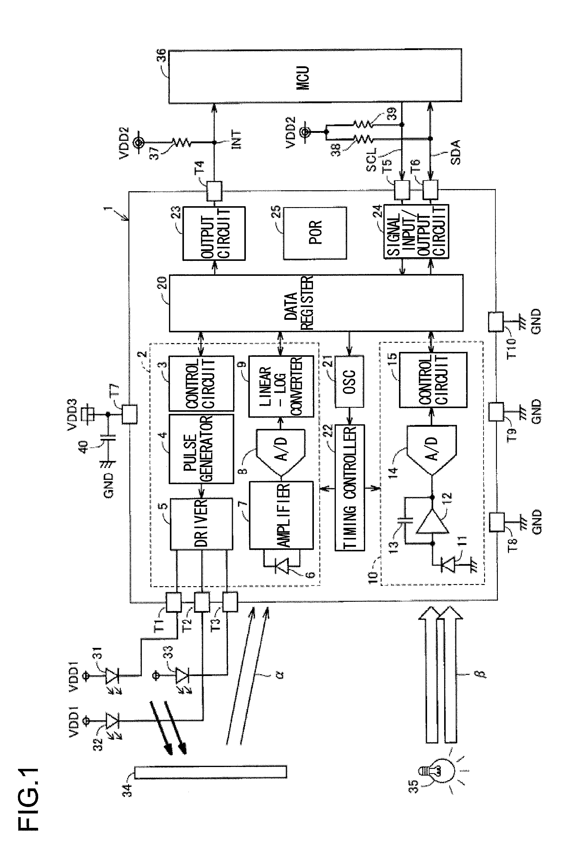
[0055]The semiconductor device 1 according to an embodiment of the present invention is provided with a proximity sensor 2, an illuminance sensor 10, a data register 20, an oscillator (OSC) 21, a timing controller 22, a signal output circuit 23, a signal input / output circuit 24, drive terminals T1 through T3, a signal output terminal T4, a clock input terminal T5, a serial data input / output terminal T6, a power supply terminal T7, ground terminals T8, T9, and a test terminal T10, as shown in FIG. 1.

[0056]The cathodes of infrared LEDs (Light Emitting Diode) 31 through 33 are connected to the drive terminals T1 through T3, respectively. The anodes of the infrared LEDs 31 through 33 each receive a power supply voltage VDD1. The proximity sensor 2 includes a control circuit 3, a pulse generator 4, a driver 5, an infrared light sensor 6, an amplifier 7, an A / D converter 8, and a linear-log converter 9. The control circuit 3 controls the proximity sensor 2 as a whole in accordance with a ...


PUM


Abstract

The calculation device (36) according to the present invention receives a plurality of reflected light intensity information for indicating the intensity of each reflected light which reaches a single light receiver via a reflecting object, the reflected light having been emitted in sequence from a plurality of light emitters (31 through 33) provided in mutually different positions, computes a phase difference of an intensity variation which occurs among the reflected light, and determines a movement of the reflecting object on the basis of the calculation result.

Description

[0001]This nonprovisional application claims priority under 35 U.S.C. §119(a) on Patent Application No. 2010-094207 filed in Japan on Apr. 15, 2010, the entire contents of which are hereby incorporated by reference.BACKGROUND OF THE INVENTION[0002]1. Field of the Invention[0003]The present invention relates to a calculation device and to a movement detection device and electronic instrument which use the calculation device, and particularly relates to a calculation algorithm for realizing a touchless motion function.[0004]2. Description of Related Art[0005]In a known mobile telephone device, a touch panel having a switch structure for performing a key operation is disposed so as to overlap with a display element for displaying a key or the like to be operated by the touch panel (see, for example, Japanese Unexamined Utility Model Application Publication No. 1-153759 (hereinafter referred to as Patent Document 1)).[0006]In another known mobile telephone device, a plurality of movemen...

Claims


Application Information

Patent Timeline
Patent Type & Authority Applications(United States)
IPC IPC(8): G09G5/00G01J5/10H01J40/14
CPCG06F3/0304G06F3/0416G06F2203/04101G06F3/0428G06F3/042G06F3/017
Inventor TSUCHIKAWA, TAKUYAUEDAIRA, YOSHITSUGUNAKATA, YUICHIROFUJINO, JUNJI
Owner ROHM CO LTD
Why Eureka
Try Eureka