Device for swept-source optical coherence domain reflectometry

a technology of optical coherence domain and reflectometry, which is applied in the field of devices for swept-source optical coherence domain reflectometry, can solve the problems of insufficient sensitivity to achieve the required measuring accuracy, failure to accelerate the rate of adjustment of reference path, and insufficient sensitivity

Active Publication Date: 2011-10-20
CARL ZEISS MEDITEC AG
View PDF1 Cites 30 Cited by
  • Summary
  • Abstract
  • Description
  • Claims
  • Application Information

AI Technical Summary

Benefits of technology

[0013]Proceeding from the prior art, it is therefore the object of the invention to specify a device with the aid of which the intraocular distances in the eye can be measured quickly and accurately, particularly even given the occurrence of typical eye movements, without exhibiting the disadvantages of an active measurement beam tracking with a sample movement such as, for example, latency time errors.

Problems solved by technology

Efforts to accelerate the rate of adjustment of the reference path, for example, by rotating prisms such as EP 1 391 781, have not been successful, since the sensitivity is not sufficient to achieve the required measuring accuracy.
The usual approaches to eliminating the problem are the extremely complicated tracking methods in which the movement of the sample is detected and the measurement beam position is tracked.
It is disadvantageous of such approaches that, despite the large technical outlay, the finite latency time of such systems always results in certain tracking errors, particularly for very fast eye movements such as saccades.

Method used


Image

  • Device for swept-source optical coherence domain reflectometry
  • Device for swept-source optical coherence domain reflectometry
  • Device for swept-source optical coherence domain reflectometry

Examples


Embodiment Construction

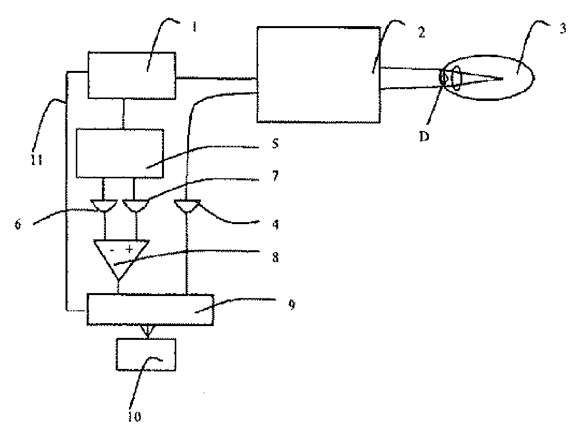
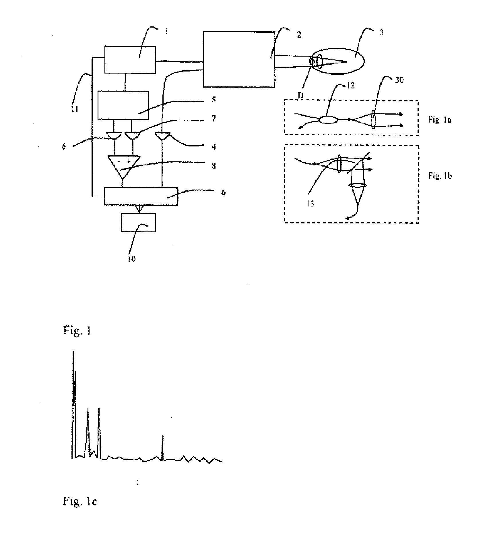
[0050]The basic design for implementing the invention in FIG. 1 consists of a suitable tunable laser 1 that is characterized by the following variables: tuning time τ, wavelength λ, spectral tuning range Δk, centroid wave number k0, and laser line width δk.

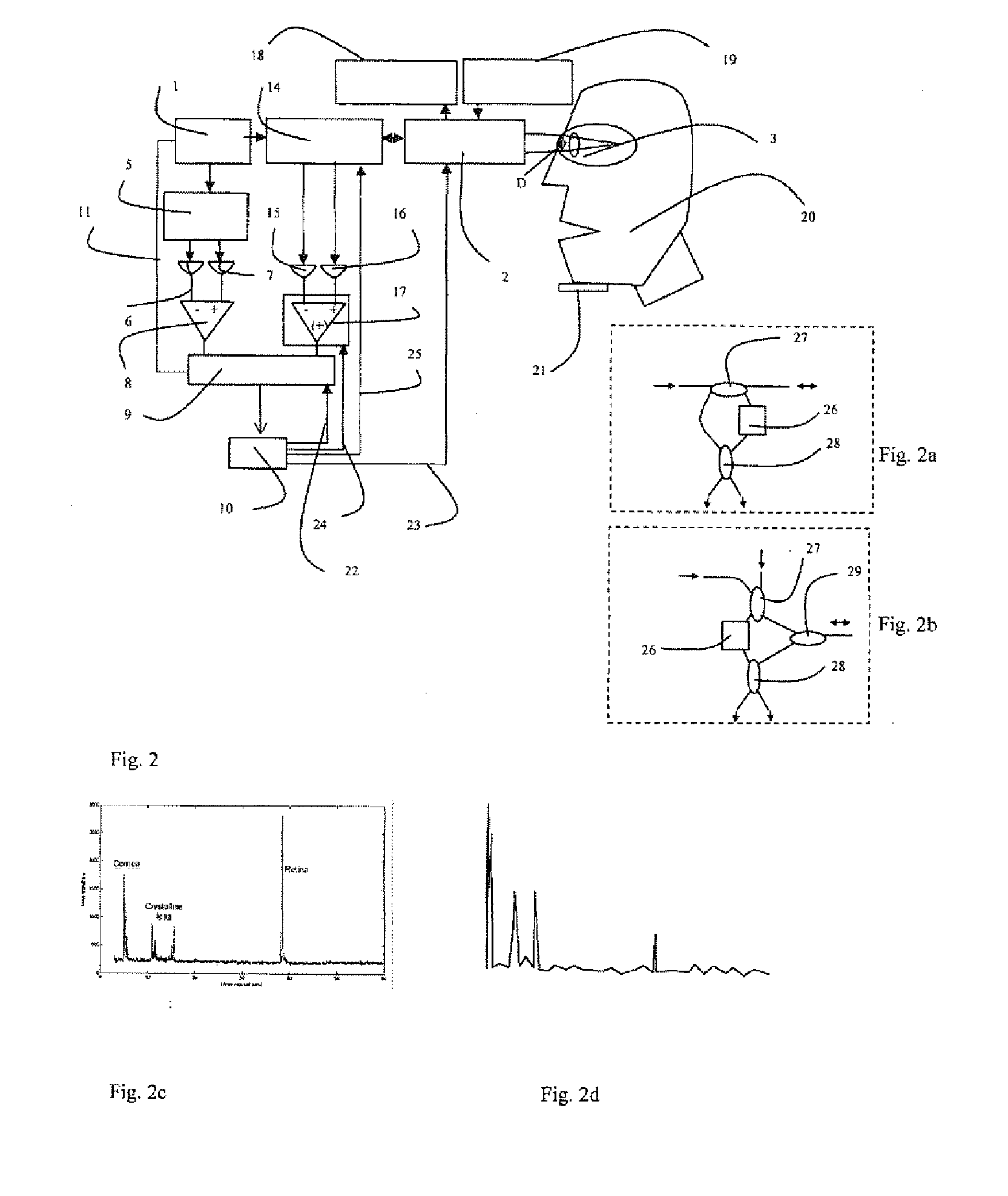
[0051]A beam shaping and coupling unit 2 serves both to direct the beam of the laser 1 onto the sample 3 (illustrated schematically here as an eye), and to feed the light backscattered by the sample 3 to a detector 4, D in this case being the diameter of the measurement beam when it impinges on the sample (here the cornea of the eye). Assigned to the laser 1 is a reference interferometer 5 whose preferred two detectors 6, 7 are connected to a data acquisition apparatus 9 via a difference amplifier 8. The detectors consist of InGaAs photodiodes with chip diameters >0.1 mm and bandwidths less than 80 MHz.

[0052]Here, the reference interferometer 5 is a fiber optic Mach-Zehnder interferometer having two outputs connected to the detect...


PUM


Abstract

A device for swept-source optical coherence domain reflectometry (SS OCDR) on moveable samples, particularly human eyes, for obtaining A-scans, having a measuring range according to the sample length and having a laser light source which can be adjusted by a main wave number k0 and at least one receiver for the light dissipated from the sample, wherein the sample is illuminated on the sample surface by a measurement beam having a diameter D by way of a coupling device. The light source has a spectral line width of δk<168 m−1 and the adjustment of the light source is carried out in τ<44 s / (D*k0).

Description

PRIORITY CLAIM[0001]The present application is a National Phase entry of PCT Application No. PCT / EP2009 / 009189, filed Dec. 21, 2009, which claims priority from German Application No 102008063225.2, filed Dec. 23, 2008, the disclosures of which are hereby incorporated by reference herein in their entirety.FIELD OF THE INVENTION[0002]The invention relates to a device for swept source optical coherence domain reflectometry such as can be applied in the optical biometry of the eye, for example.BACKGROUND[0003]The optimal matching of an artificial intraocular lens requires knowledge of the optical conditions in the patient's eye, in particular the distances between the cornea, crystalline lens and retina.[0004]After this determination of position was originally carried out by means of ultrasound, a device operating optically and without making contact has been introduced in the form of the IOL Master of Carl Zeiss. The functional principle is based in this case on the so called time doma...

Claims


Application Information

Patent Timeline
Patent Type & Authority Applications(United States)
IPC IPC(8): A61B3/10G01B9/02
CPCA61B3/102G01N21/4795G01B9/02004G01B9/0203A61B3/1005G01B9/02067G01B9/02069G01B2290/45G01B9/02091
Inventor HACKER, MARTINEBERSBACH, RALFPABST, THOMASPETERLEIN, ULFANTKOWIAK, GERARDBERGNER, ROLANDKOSCHMIEDER, INGO
Owner CARL ZEISS MEDITEC AG
Why Eureka
Try Eureka