Printing relief plate producing apparatus, system, method, and recording medium

a printing relief plate and producing apparatus technology, applied in printing, instruments, visual presentation, etc., can solve the problems of printing density shift, high dot gain and graininess, engraving accuracy and print reproducibility, etc., and achieve the effect of stable printing density

Inactive Publication Date: 2011-10-20
FUJIFILM CORP
View PDF2 Cites 25 Cited by
  • Summary
  • Abstract
  • Description
  • Claims
  • Application Information

AI Technical Summary

Benefits of technology

[0016]An object of the present invention is to provide a printing relief plate producing apparatus, a printing relief plate producing system, a printing relief plate producing method, and a

Problems solved by technology

Flexography has been problematic in that, since the used plate materials are elastic, halftone dots that are printed tend to be large in size, resulting in high dot gain and graininess (i.e., density fluctuations indicative of image coarseness).
However, the printing relief plates disclosed in Japanese Laid-Open Patent Publication No. 2008-230195, Japanese Laid-Open Patent Publication No. 2008-183888, Japanese Laid-Open Patent Publication No. 2007-185917, and Japanese Laid-Open Patent Publication No. 2006-095931 pose certain problems related to engraving accuracy and print reproducibility, if the height (engraving lowering quantity) of the convexities for all of the halftone dots is change

Method used


Image

  • Printing relief plate producing apparatus, system, method, and recording medium
  • Printing relief plate producing apparatus, system, method, and recording medium
  • Printing relief plate producing apparatus, system, method, and recording medium

Examples


first embodiment

[0075]First, a printing relief plate producing apparatus according to the present invention will be described in detail below with reference to FIGS. 1 through 13.

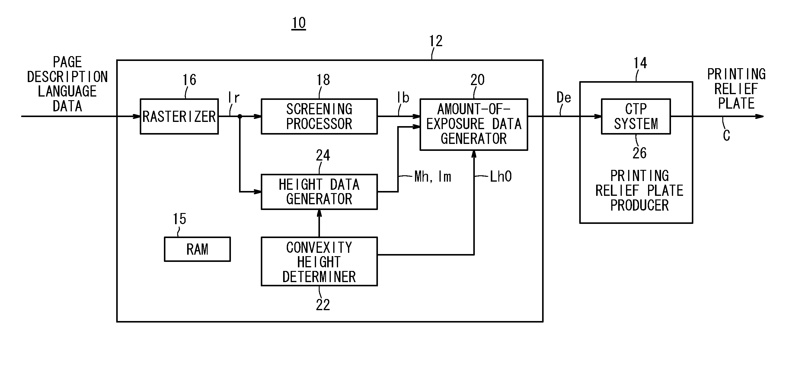
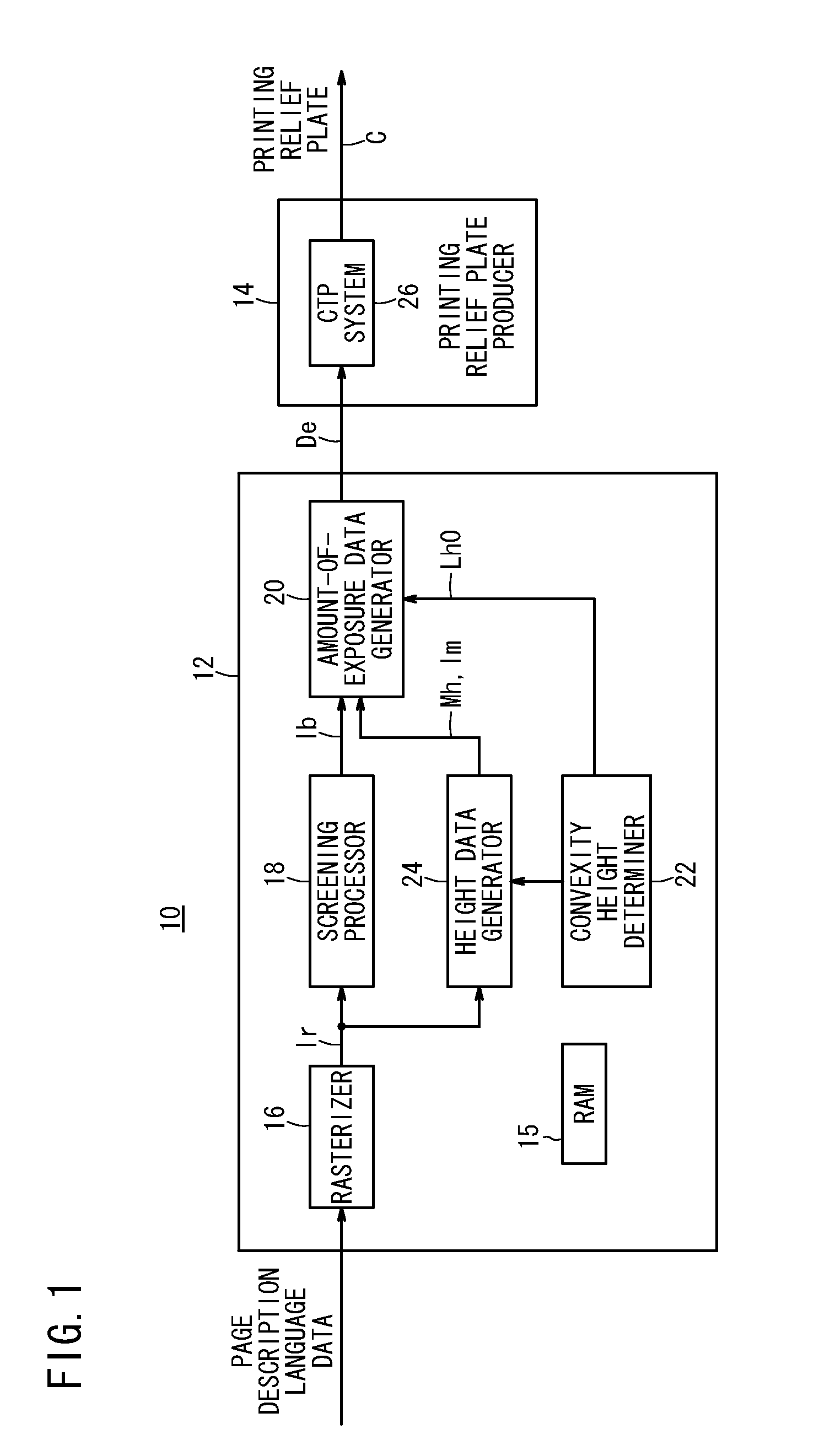
[0076]FIG. 1 is a block diagram of a platemaking apparatus (printing relief plate producing apparatus) 10 according to a first embodiment of the present invention. As shown in FIG. 1, the platemaking apparatus 10 basically comprises a RIP (Raster Image Processor) 12 and a printing relief plate producer 14.

[0077]The RIP 12 includes a rasterizer 16, a screening processor (binary image data generator) 18, an amount-of-exposure data generator 20, a convexity height determiner 22, and a height data generator 24.

[0078]The rasterizer 16 converts PDL (Page Description Language) data, such as PDF (Portable Document Format) data, PS (PostScript: registered trademark) data, or the like, which represent vector images of printed documents edited using a computer or the like, into raster image data Ir.

[0079]The raster image data Ir comp...

second embodiment

[0150]FIG. 14 is a block diagram of a platemaking system 310 (printing relief plate producing system) 310 according to the present invention. As shown in FIG. 14, the platemaking system 310 basically comprises a RIP (Raster Image Processor) 312 and a printing relief plate producer 314.

[0151]The RIP 312 includes a rasterizer 16 and a screening processor 18. The printing relief plate producer 314 includes an amount-of-exposure data generator 320, a convexity height determiner 322, a changing data generator 324, an amount-of-exposure data changer 325, and a CTP system 26. Among the components of the printing relief plate producer 314, the amount-of-exposure data generator 320, the convexity height determiner 322, the changing data generator 324, or the amount-of-exposure data changer 325 may be implemented by a CPU (not shown), which executes a program read from a RAM 315 (recording medium).

[0152]The RIP 312 according to the second embodiment differs from the RIP 12 (see FIG. 1) accord...


PUM


Abstract

Height conversion matrices for determining heights of halftone dot convexities are generated based on raster image data. Based on the height conversion matrices and binary image data, amount-of-exposure data are generated in order to produce a printing relief plate in which the halftone dot convexities have heights at a plurality of height levels in a screen tint region, which is formed based on the binary image data. Based on the amount-of-exposure data, a printing plate material is exposed to a light beam, thereby producing a printing relief plate.

Description

CROSS-REFERENCE TO RELATED APPLICATION[0001]This application is based upon and claims the benefit of priority from Japanese Patent Application No. 2010-097199 filed on Apr. 20, 2010, of which the contents are incorporated herein by reference.BACKGROUND OF THE INVENTION[0002]1. Field of the Invention[0003]The present invention relates to a printing relief plate producing apparatus, a printing relief plate producing system, a printing relief plate producing method, and a recording medium for producing a printing relief plate having a plurality of halftone dot convexities for transferring an ink to a print medium to print halftone dots thereon.[0004]2. Description of the Related Art[0005]Heretofore, printing relief plates have been used in flexography, for example. As well known in the art, flexography uses elastic plate materials together with aqueous and UV inks. Since the plate materials are elastic, they lend themselves to printing on corrugated cardboard materials having surface i...

Claims


Application Information

Patent Timeline
IPC IPC(8): B41M1/00B41C1/04
CPCB41C1/05
Inventor SHIGETA, NORIMASASHIMAZAKI, OSAMU
Owner FUJIFILM CORP
Why Eureka
Try Eureka