Three stage scroll vacuum pump

a vacuum pump and three-stage technology, applied in the direction of machines/engines, couplings, liquid fuel engines, etc., can solve the problems of difficult and expensive manufacturing of oil free or oil less scroll compressors and vacuum pumps, limited to a single stage of compression, and links cannot be used in an oil free piece of equipment. achieve the effect of accelerating heat transfer

Active Publication Date: 2011-10-20
AIR SQUARED
View PDF6 Cites 24 Cited by
  • Summary
  • Abstract
  • Description
  • Claims
  • Application Information

AI Technical Summary

Benefits of technology

[0010]Accordingly, the present invention improves a three stage vacuum pump and other related equipment with three stages of fixed scrolls and orbiting scrolls and each stage operates simultaneously. A motor drives the second orbiting scroll within the third fixed scroll as the third stage upon three equally spaced idlers. One idler then transmits rotation and torque into the second stage, that is, the second orbiting scroll. The second orbiting scroll has involutes upon both surfaces. The second orbiting scroll engages the second fixed scroll inwardly of the invention for the second stage. In the first stage, the second orbiting scroll engages a first fixed scroll outwardly from the center of the invention. The first fixed scroll of the first stage has fins upon its back surface that extend outwardly from the invention into the atmosphere for heat transfer as the invention is strictly air cooled. The present invention also includes a fan outside the housing to accelerate heat transfer. The scrolls receive torque and rotation directly from a motor or alternatively from a motor and a magnetic coupling or magnetic face seal so that the atmosphere does not infiltrate the housing of the three stages of scrolls. The present invention also has an enclosed inlet plenum to prevent mixture or infiltration of the working fluid into the heated fluid inside the housing.
[0013]It is a still further object of the present invention to provide air cooling of the vacuum pump thus increasing its efficiency.
[0018]And, It is a still further object of the present invention to provide an enclosed inlet plenum that prevents mixing or infiltration of the working fluid into the heated fluid inside the housing.

Problems solved by technology

In general, they have been limited to a single stage of compression due to the complexity of two or more stages.
Oil free or oil less scroll type compressors and vacuum pumps have difficult and expensive manufacturing, due to the high precision of the scroll in each compressor and pump.
Such links cannot be used in an oil free piece of equipment because of the friction and wear upon the scrolls.
If the fixed and orbiting scrolls in oil free equipment lack precision, leakage will occur and the equipment performance will decline as vacuums take longer to induce or do not arise at all.
However, industry, science, and research still demand compact vacuum pumps that can achieve higher vacuums.

Method used


Image

  • Three stage scroll vacuum pump
  • Three stage scroll vacuum pump
  • Three stage scroll vacuum pump

Examples


Embodiment Construction

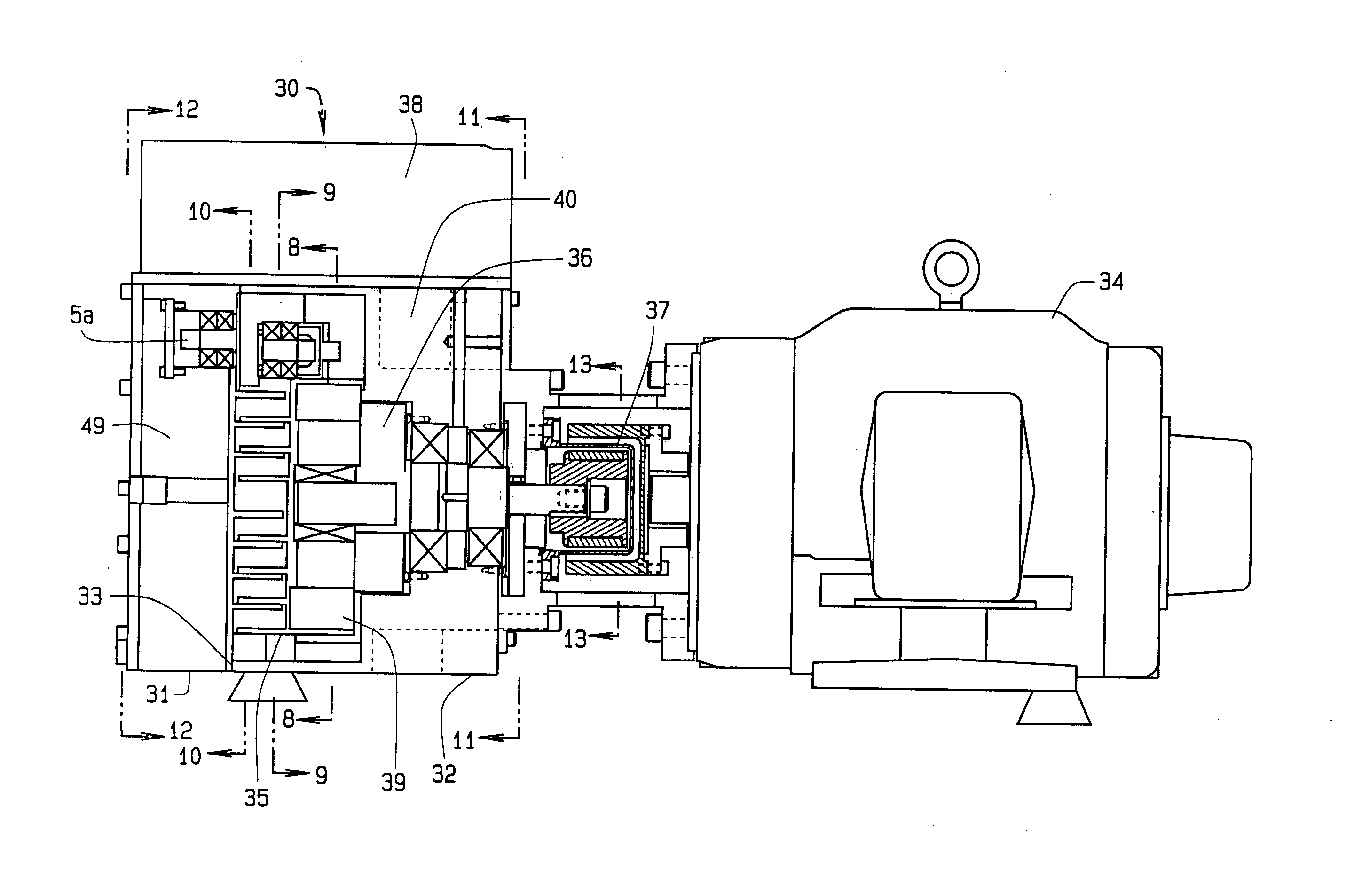
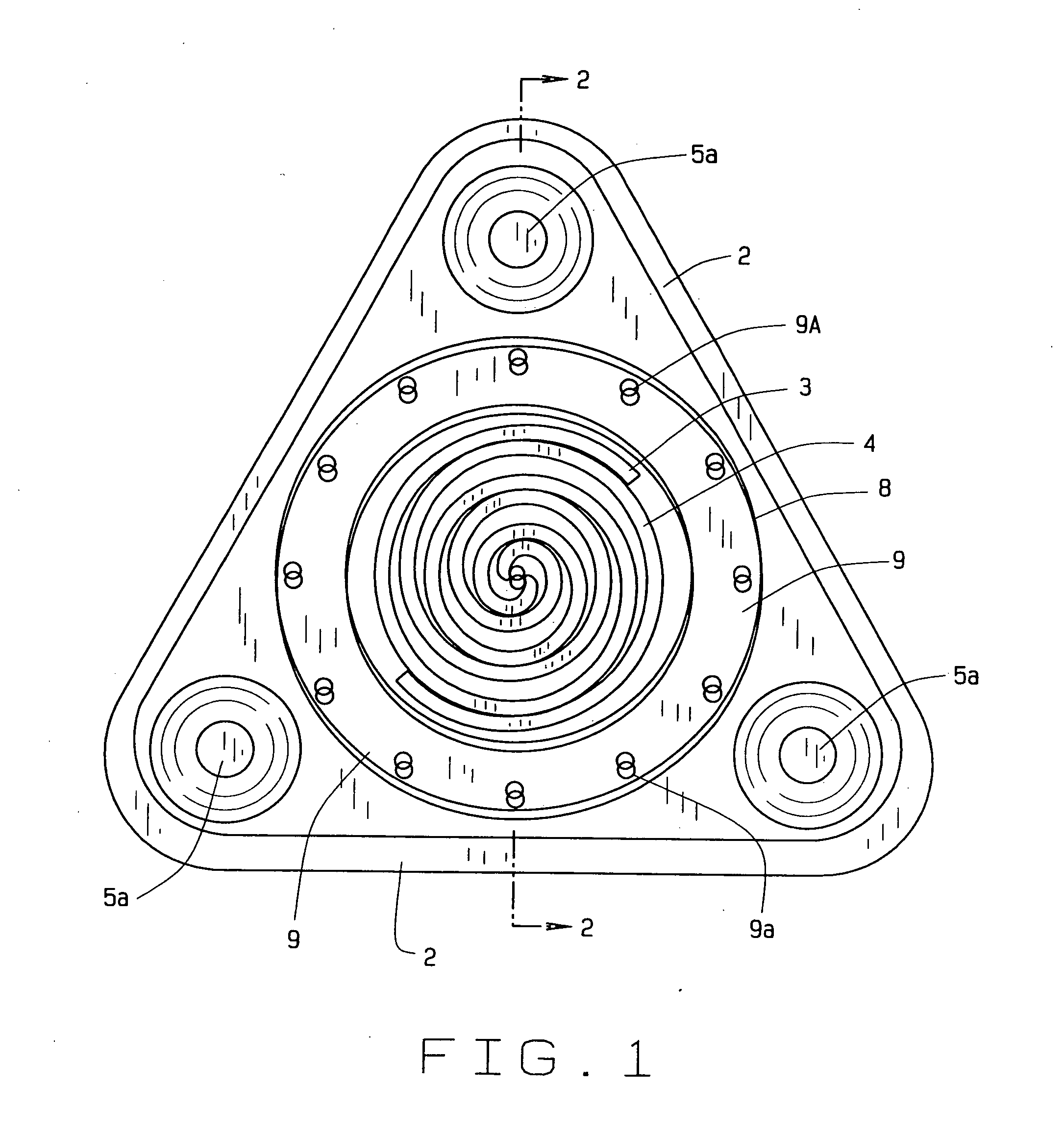
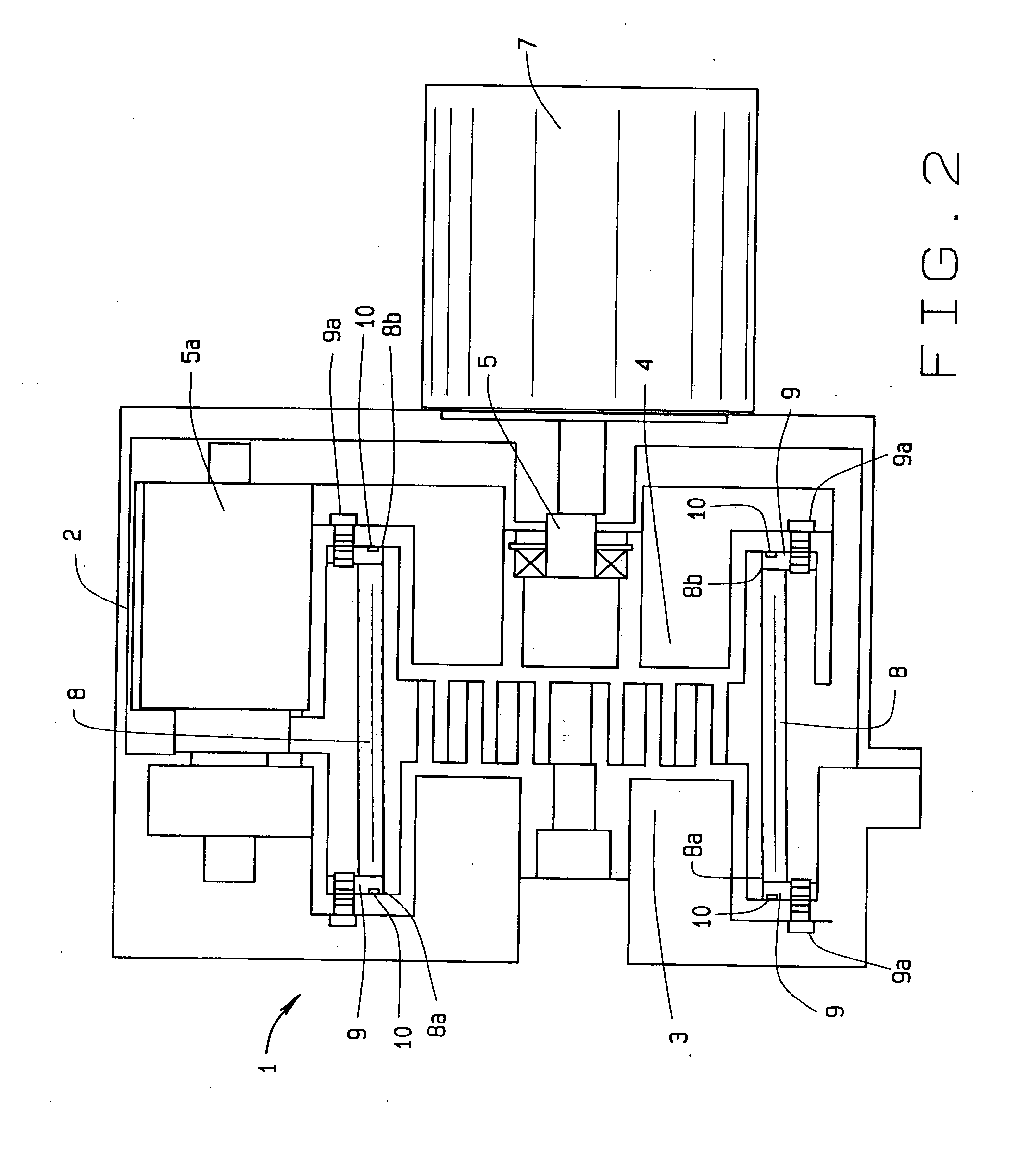
[0040]An alternate embodiment of the invention overcomes the prior art limitations by modifying scroll compressors and other pumps with bellows, liquid cooling using bellows, and tip seals. Turning to FIG. 1, a scroll compressor 1 appears in a sectional view through the scrolls. The scroll compressor 1 has a case 2 to contain the compressor 1 and scrolls. Within the case 2, the alternate embodiment of the invention has at least three equally spaced idlers 5aa. The idlers rotate eccentrically in cooperation with the scrolls as the scrolls compress or evacuate a gas from a container, not shown. The scrolls are located within the idlers and intermesh. The scrolls have a fixed scroll 3 of a generally spiral shape fixed to the compressor 1 and an orbiting scroll 4 also of a generally spiral shape. The orbiting scroll 4 fits within the fixed scroll 3 and as the orbiting scroll 4 turns, gas is drawn into the scrolls and evacuated from the compressor 1. A bellows 8 surrounds and seals the s...


PUM


Abstract

A three stage vacuum pump has three stages of fixed scrolls and orbiting scrolls that operate simultaneously. A motor drives the second orbiting scroll within the third fixed scroll upon three equally spaced idlers. One idler then transmits rotation and torque into the second stage. The second orbiting scroll to has involutes upon both surfaces to engage the second fixed scroll inwardly and the first fixed scroll outwardly. The first fixed scroll has fins upon its back that extend into the atmosphere to transfer heat to air cool the invention. This pump also has a fan accelerating heat transfer. The pump operates the scrolls directly from a motor or from a motor and magnetic coupling so that the atmosphere does not infiltrate the pump.

Description

CROSS REFERENCE TO RELATED APPLICATION[0001]This non provisional patent application claims priority to the provisional patent application having Ser. No. 61 / 342,690, which was filed on Apr. 16, 2010, which claims priority to the pending provisional application have Ser. No. 61 / 336,035 filed on Jan. 16, 2010 and claims priority to the pending non-provisional patent application having Ser. No. 11 / 703,585 which was filed on Feb. 6, 2007 and which claims priority to the expired provisional patent application having Ser. No. 60 / 773,274, which was filed on Feb. 14, 2006 which was filed during the pendency of PCT application Serial No. PCT / US01 / 50377 which was filed on Dec. 31, 2001 designating the U.S. and during the pendency of PCT application Serial No. PCT / US01 / 43523 which was filed on Nov. 16, 2001 designating the U.S., and which claimed priority to the U.S. non-provisional application Ser. No. 09 / 751,057 which was filed on Jan. 2, 2001, now U.S. Pat. No. 6,511,308, and which claimed ...

Claims


Application Information

Patent Timeline
Patent Type & Authority Applications(United States)
IPC IPC(8): F04C23/00
CPCF04C18/0223F04C23/001F04C2/025F04C29/0064F04C29/04F04C25/02F04C29/0085F04C18/0215F04C18/0269F04C23/005F04C29/005
Inventor SHAFFER, ROBERT W.
Owner AIR SQUARED
Why Eureka
Try Eureka