Method and apparatus for performing pattern reconnection after individual or multipart alignment

a multi-part alignment and pattern technology, applied in the field of laser pattern imaging of workpieces, can solve the problems of difficult to achieve desired overlay performance with conventional aligners, large takt penalty of conventional approach, and lack of specific problems in prior art stacks with dies, so as to avoid edge roughness and bad connections

Active Publication Date: 2011-10-20
MICRONIC LASER SYST AB
View PDF0 Cites 18 Cited by
  • Summary
  • Abstract
  • Description
  • Claims
  • Application Information

AI Technical Summary

Benefits of technology

[0029]The more specific problem aspect as stated above is solved by aligning accurately with strict alignment requirements in first, sacred zones and aligning with less strict alignment requirements in a second, stretch zone according to the inventive concept enables individual alignment to each die (component), while avoiding edge roughness and bad connections for lines that should connect the dies with each other or with other layers.

Problems solved by technology

However, random positional errors for a die make it relatively difficult to achieve desired overlay performance with conventional aligners.
However, this conventional approach has a relatively large takt penalty because realigning for each shot is necessary.
However, this piece of prior art lacks disclosure of application in stack with dies and solutions addressing specific problems in this application.
With transformation of a pattern to individual dies differences in the individual transformations may create edge roughness or even bad connections for lines in the pattern that are intended to connect dies to each other or to other layers.
This makes it unsuitable or even impossible to individually align to each die with the normal current quality requirements.

Method used


Image

  • Method and apparatus for performing pattern reconnection after individual or multipart alignment
  • Method and apparatus for performing pattern reconnection after individual or multipart alignment
  • Method and apparatus for performing pattern reconnection after individual or multipart alignment

Examples


Embodiment Construction
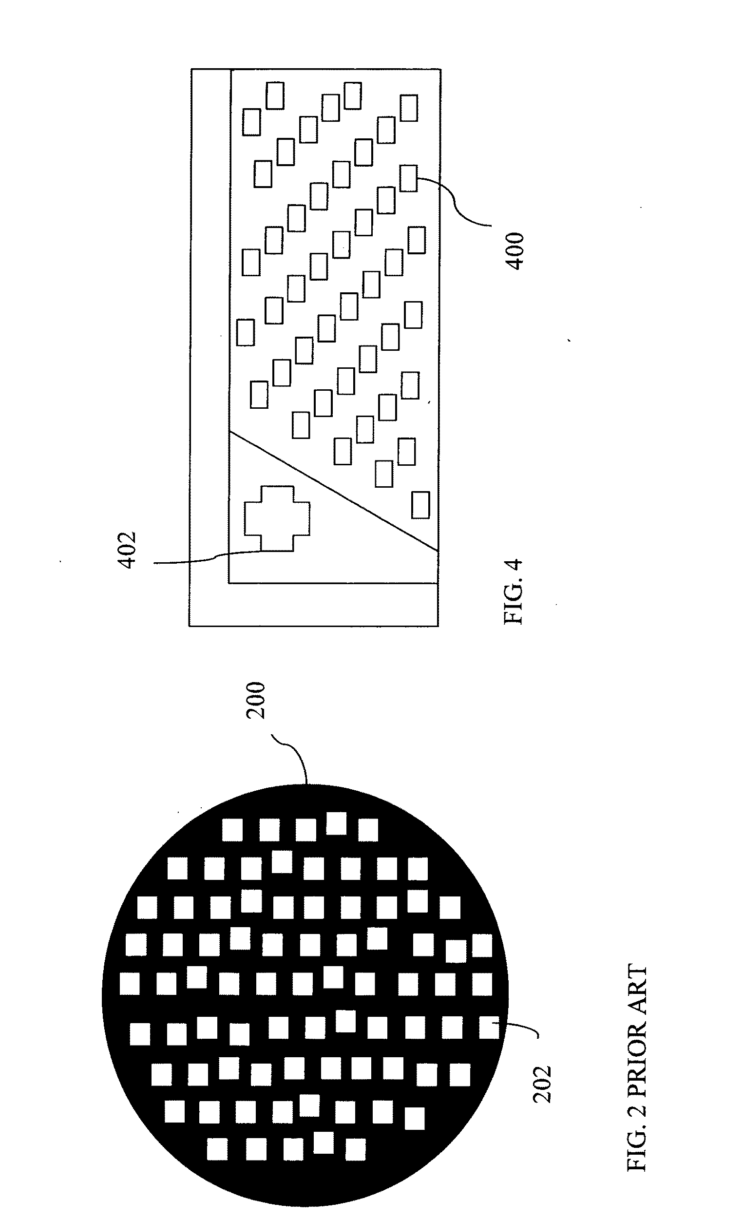
Workpiece

[0061]For the purpose of this application text the term workpiece is used to denominate any carrier of a surface layer upon which a pattern can be printed with a laser direct imaging system. For example a silicon substrate or a silicon wafer for a printed circuit board workpiece, or an organic substrate. Workpieces may have any shape, such as circular, rectangular or polygonal, and may have any size for example in a piece or in a roll.
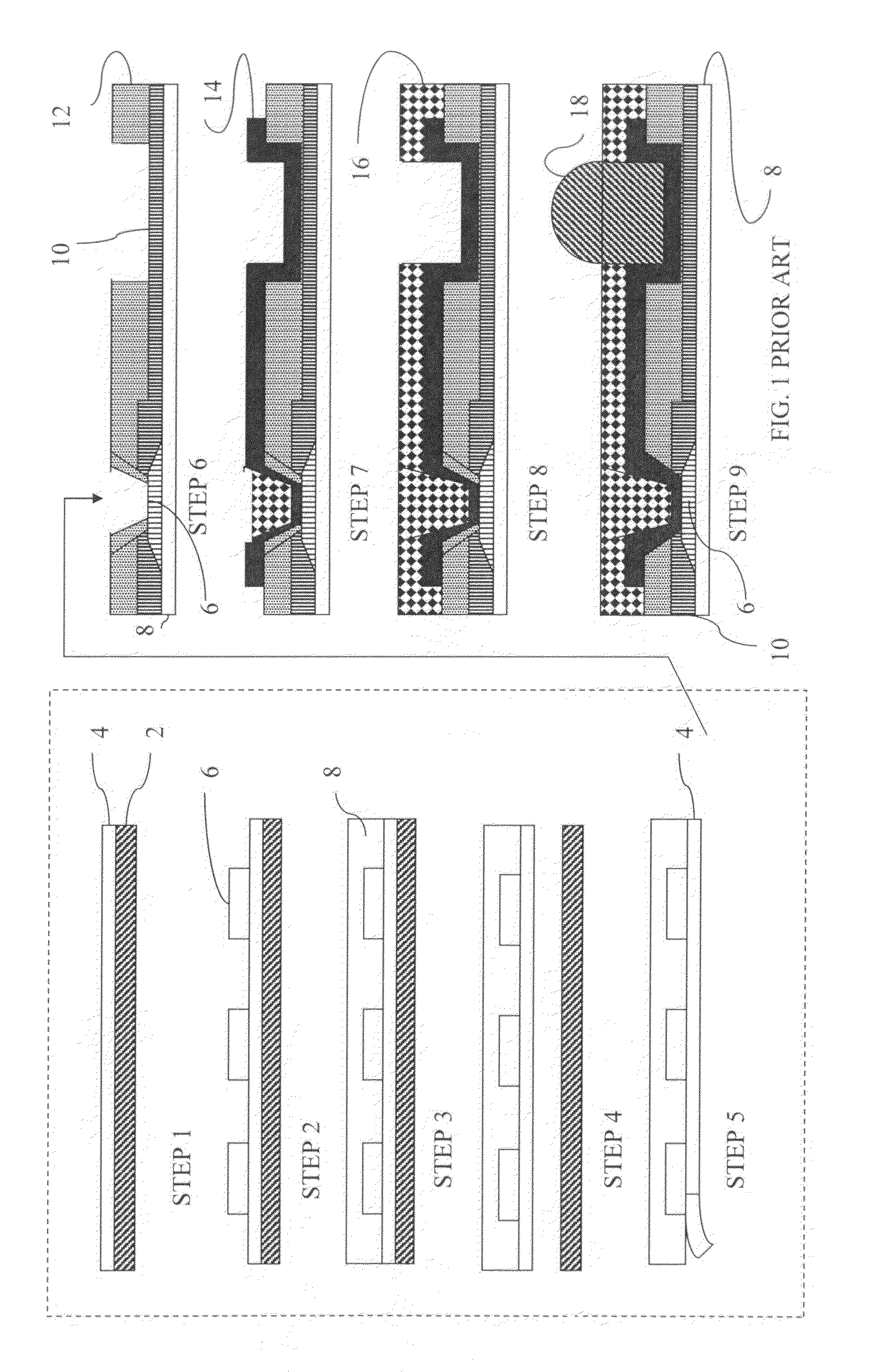
Die

[0062]For the purpose of this application text the term die is used to denominate a passive component, an active component, or any other component associated with electronics. For example, a die may be a small block of semiconducting material, on which a given functional circuit is fabricated.
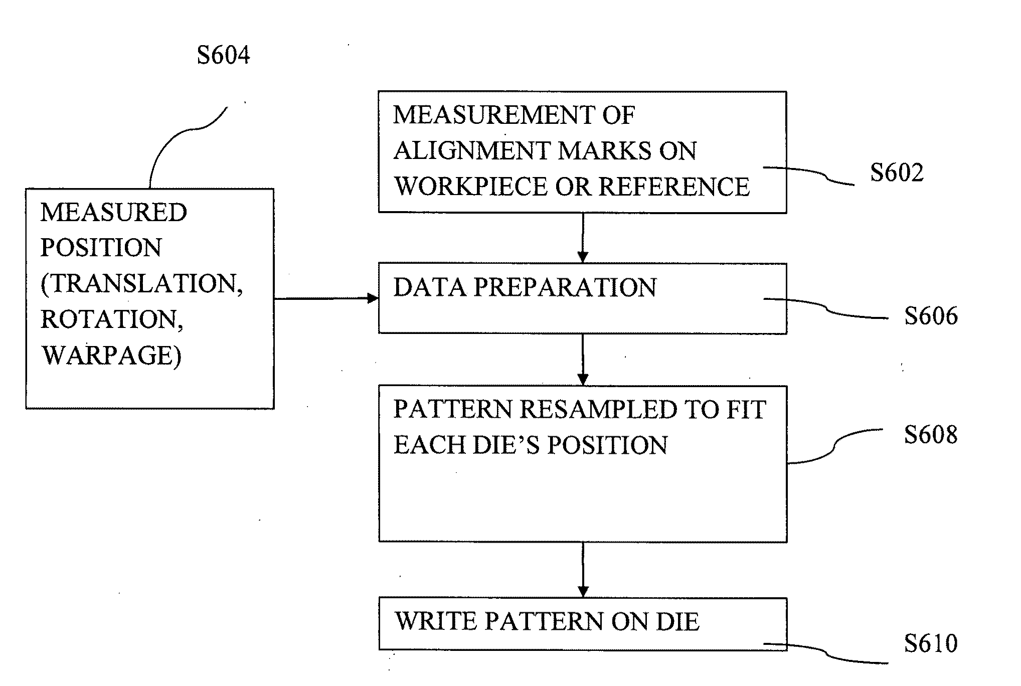
Local Alignment

[0063]For the purpose of this application text the term local alignment is used to denominate alignment in relation to alignment features, for example alignment marks, on an individual die or on a group of dies.

Global Alignment

[0064]For ...


PUM


Abstract

A method for patterning a second layer of a work piece in a direct write machine in the manufacturing of a multilayer system-in-package stack. The work piece having a first layer with a plurality of electrical components in the form of dies arbitrarily placed. Each component having connection points where some need to be connected between the components. A first pattern wherein different zones comprising connection points of dies distributed in the first layer are associated with different requirements on alignment. The method comprising the steps of: a. Detecting sacred zones in first pattern that have a high requirement on alignment to selected features of the system-in-package stack or to the placed components; b. Detecting stretch zones of the first pattern that are allowed to have a lower requirement on alignment to other features of the system-in-package stack; c. Transforming the first pattern by calculating adjusted first pattern data comprising transformation of the original circuit pattern such that: i. connection points in adjacent sacred zones are aligned within a pre-settable alignment deviation parameter; and such that ii. deviations between the positions of corresponding connection points in the sacred zones are compensated for in the pattern for connection points of the stretch zones; d. writing a pattern on the layer of the work piece according to the adjusted pattern data. The first pattern may also be simultaneously matched to a second pattern.

Description

CROSS-REFERENCE TO RELATED APPLICATIONS[0001]This non-provisional U.S. patent application claims priority under 35 U.S.C. §119(e) to provisional U.S. patent application No. 61 / 282,561, filed on Mar. 1, 2010, provisional U.S. patent application No. 61 / 282,547, filed on Feb. 26, 2010, provisional U.S. patent application No. 61 / 323,047, filed on Apr. 12, 2010, provisional U.S. patent application No. 61 / 323,048, filed on Apr. 12, 2010, and provisional U.S. patent application No. 61 / 323,685, filed on Apr. 13, 2010, the entire contents of all of which are incorporated herein by reference.TECHNICAL FIELD OF THE INVENTION[0002]The present invention relates in general to laser pattern imaging of workpieces in the manufacturing of products comprising patterning of a photosensitive surface employing a laser direct imaging device. More particularly, the present invention relates to methods and apparatuses for performing pattern reconnection after alignment of pattern to individual or multiple c...

Claims


Application Information

Patent Timeline
Patent Type & Authority Applications(United States)
IPC IPC(8): G06F17/50
CPCG03F7/70383H05K3/4679G03F9/7003
Inventor WAHLSTEN, MIKAELGUSTAFSSON, PER-ERIK
Owner MICRONIC LASER SYST AB
Why Eureka
Try Eureka