System and method for multi-carrier multiplexing

a multi-carrier and multiplexing technology, applied in the field of multi-carrier multiplexing, can solve the problems of high power consumption and expensive equipment, and achieve the effect of low power consumption and increased efficiency

Inactive Publication Date: 2011-10-20
HUGHES NETWORK SYST
View PDF2 Cites 13 Cited by
  • Summary
  • Abstract
  • Description
  • Claims
  • Application Information

AI Technical Summary

Benefits of technology

[0012]What is needed is a system and method to increase the efficiency and address the challenges of transmitting high qu...

Problems solved by technology

High capacity data services over satellite are among the primary technology challenges facing the industry and satellite system operators today.
To achieve high data rates, fo...

Method used


Image

  • System and method for multi-carrier multiplexing
  • System and method for multi-carrier multiplexing
  • System and method for multi-carrier multiplexing

Examples


Embodiment Construction

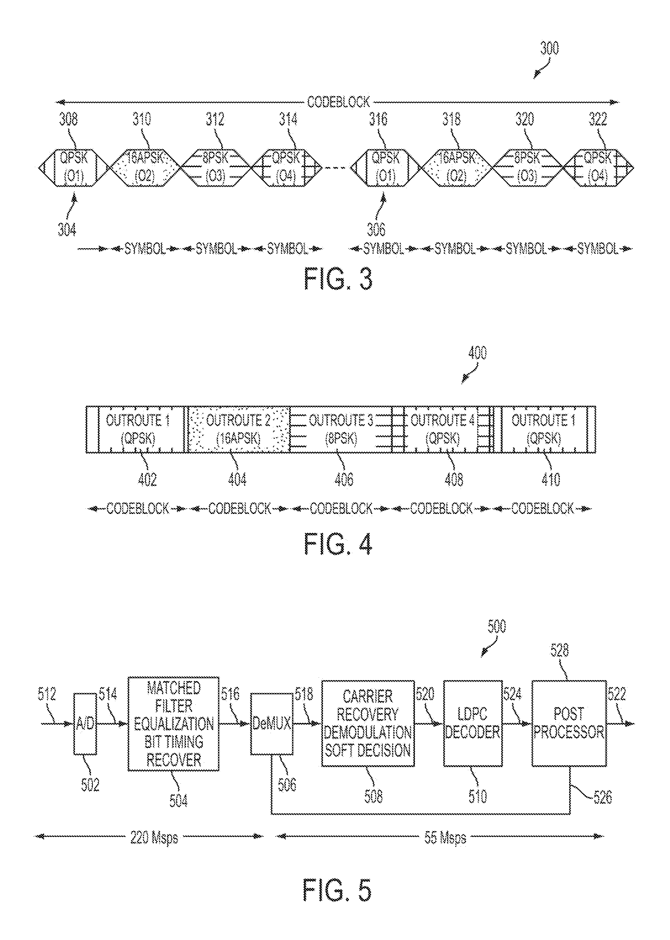
[0035]In accordance with an aspect of the present invention, a plurality of outroute data streams may be multiplexed at the transmitter side, thereby achieving multiple times greater data capacity than existing transmitters. Similarly, a received multiplexed data stream may be demultiplexed at the receiver side in order to achieve greater data capacity.

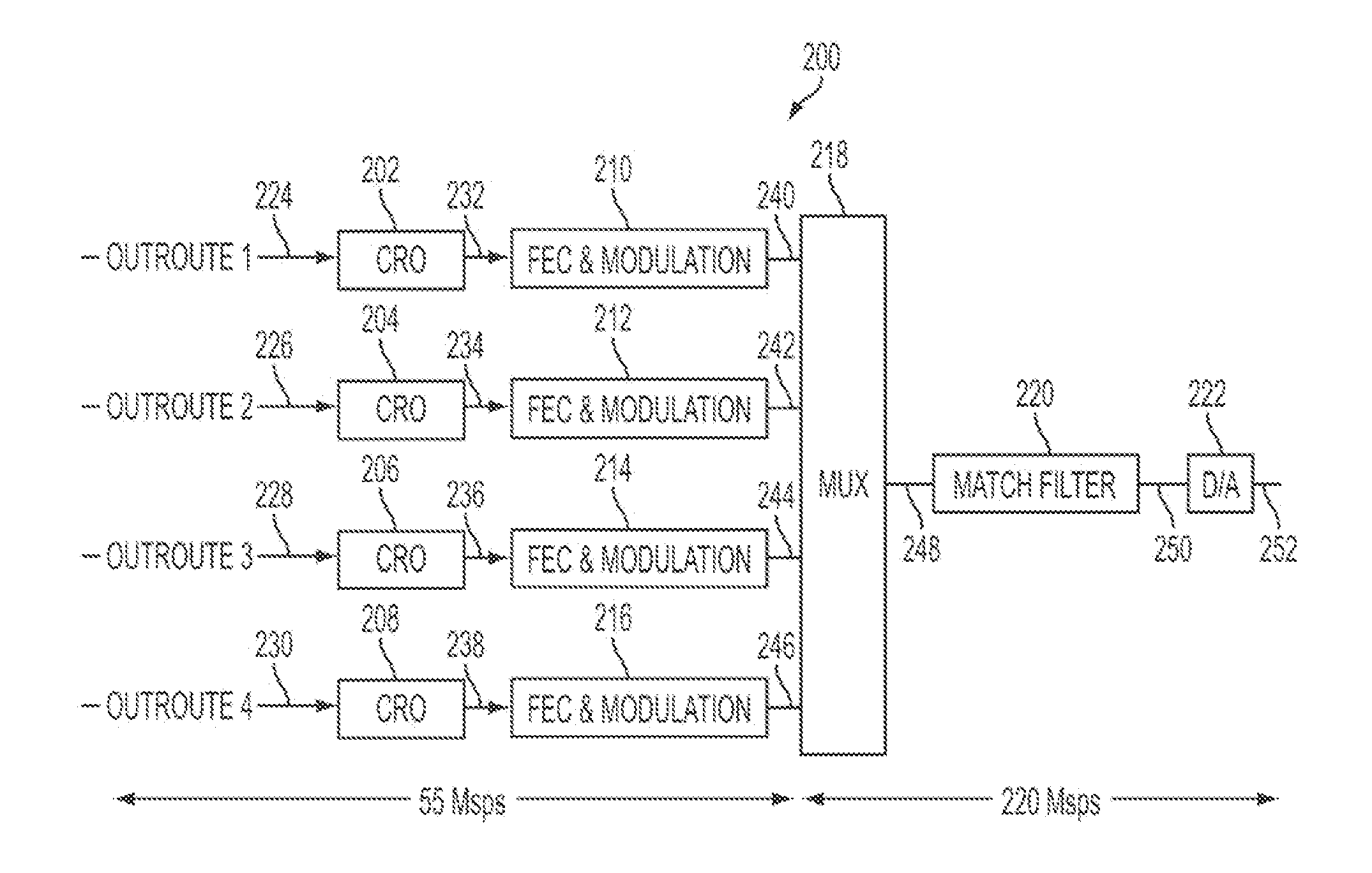
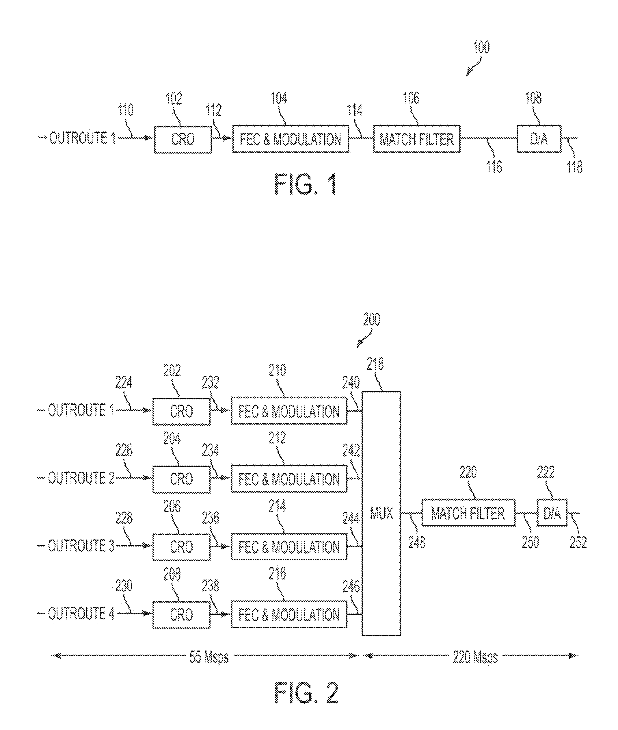
[0036]In an example embodiment, a transmitter has a four outroute streams, multiplexed into one 220 Msps outroute stream. The outroute streams may be multiplexed with either a Time Division Multiplexing (TDM) scheme or a Code Division Multiplexing (CDM) scheme, that can be sent over the satellite system. Before being multiplexed, each outroute stream may be coded with a relatively low rates, for example 55 Msps. Example transmitters in accordance with aspects of the present invention will now be described with reference to FIGS. 2-4.

[0037]FIG. 2 illustrates an example transmitter, in accordance with an aspect of the present invention....


PUM


Abstract

A transmitter is provided for use with a first input signal and a second input signal. The transmitter includes a first modulating portion, a second modulating portion and a multiplexing portion. The first modulating portion can output a first plurality of code blocks based on the first input signal, wherein each of the first plurality of code blocks has a first sequence number associated therewith and is modulated with a first modulation scheme. The second modulating portion can output a second plurality of code blocks based on the second input signal, wherein each of the second plurality of code blocks has a second sequence number associated therewith and is modulated with a second modulation scheme, and wherein the second modulation scheme is different than the first modulation scheme. The multiplexing portion can a third plurality of code blocks based on the first plurality of code blocks, the second plurality of code blocks and planning code block. The planning code block associates each of the third plurality of code blocks with a respective one of the first plurality of code blocks and the second plurality of code blocks.

Description

[0001]The present application claims priority from U.S. Provisional Application No. 61 / 324,085 filed Apr. 14, 2010, the entire disclosure of which is incorporated herein by reference.BACKGROUND[0002]Transportation of higher throughput advanced services via a satellite transponder has been an engineering design constraint for decades. The transmission system and receiver system are main two areas of a satellite broadcast system. High capacity data services over satellite are among the primary technology challenges facing the industry and satellite system operators today. Digital video broadcast—satellite second generation (DVB-S2) is an enhanced specification for satellite digital television broadcast developed in 2003 and ratified in March 2005. Using the traditional mechanism over the standard DVB-S2, meeting the high bandwidth and interactive services requires significantly higher satellite transponders to support data rates.[0003]FIG. 1 illustrates an example conventional transmi...

Claims


Application Information

Patent Timeline
IPC IPC(8): H04N7/20
CPCH04N7/20
Inventor ANTIA, YEZDIROOS, DAVIDBECKER, NEAL
Owner HUGHES NETWORK SYST
Why Eureka
Try Eureka