Lubricating System for a Two-Stroke Engine

Inactive Publication Date: 2011-10-27
HERZER BERNARDO +2
View PDF6 Cites 10 Cited by
  • Summary
  • Abstract
  • Description
  • Claims
  • Application Information

AI Technical Summary

Benefits of technology

[0009]The present invention reduces the number of parts and reduces the potential for oil leaks between the joints, particularly in the oil supply line, where the pressure is higher than atmospheric. The additional improvement to the oil pump design simplifie

Problems solved by technology

The disadvantage with pre-mixing is that the ratio of fuel to oil is very much dependent on the manufacturer, duty cycle of the engine, and model of the equipment.
Having to use different ratios for different engines/models can confuse the user as to how much oil has to be mixed with the fuel.
Secondly, if the ratio of fuel to oil is not correct the engine will either be overly lubricated or under lubricated

Method used


Image

  • Lubricating System for a Two-Stroke Engine
  • Lubricating System for a Two-Stroke Engine
  • Lubricating System for a Two-Stroke Engine

Examples


Example

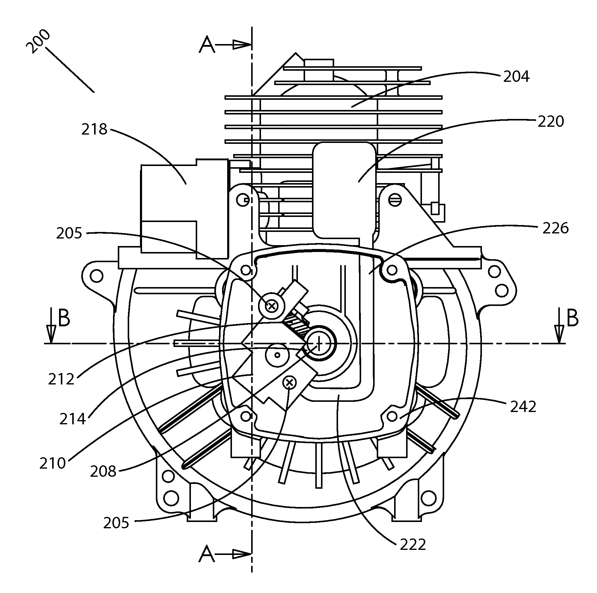
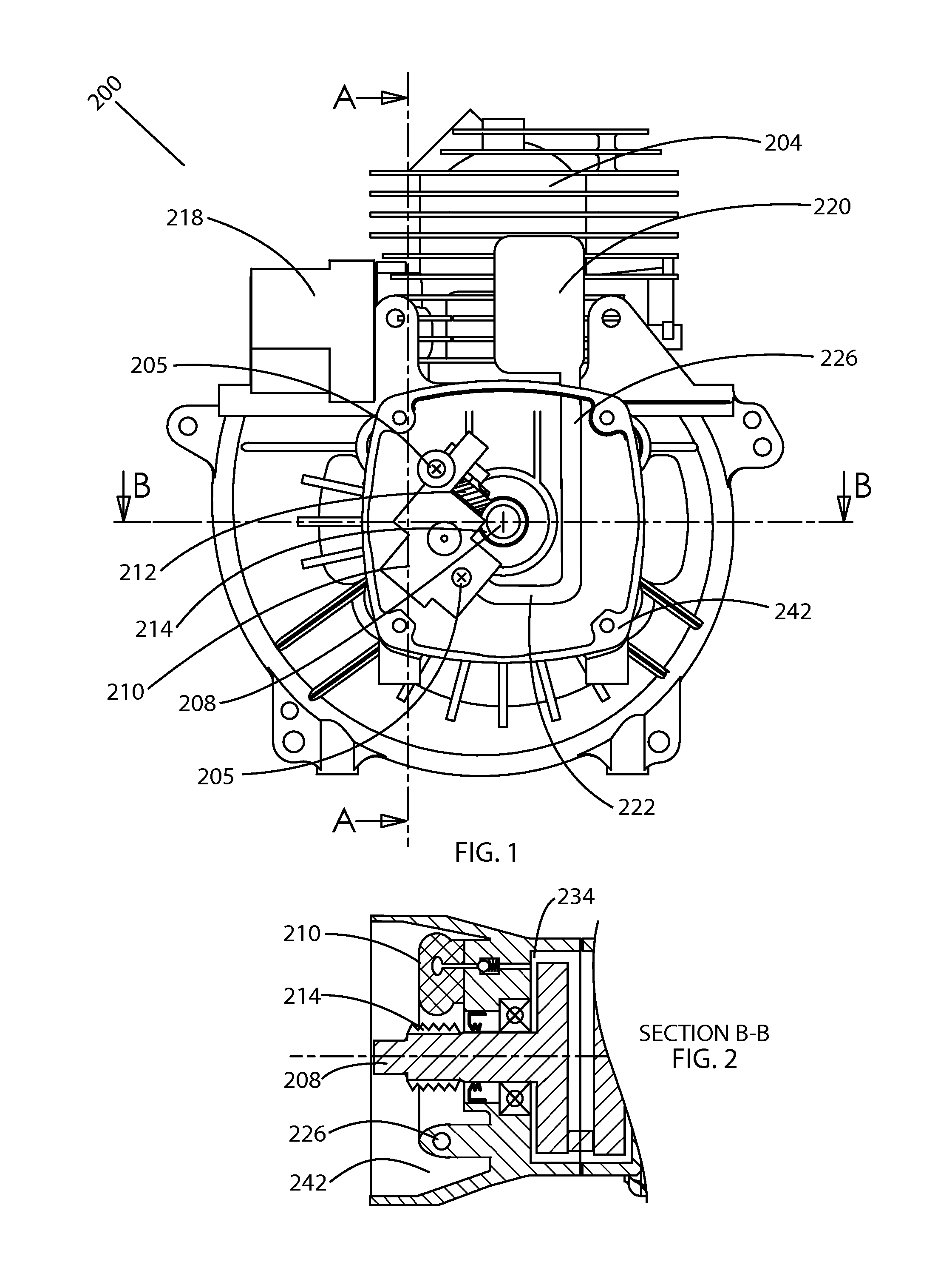
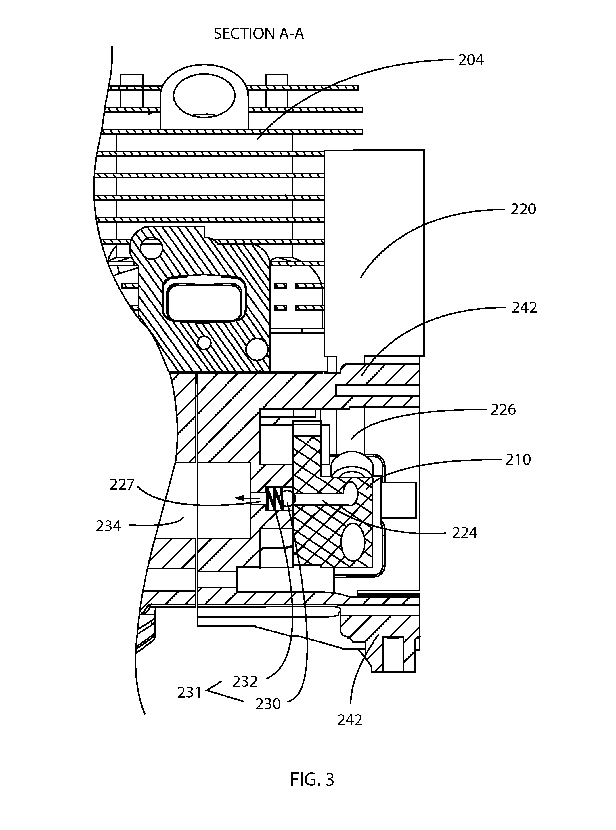
[0020]FIG. 1 is an embodiment of the present invention. FIG. 1 shows an oil injected two-stroke engine 200 having an oil tank 220, and an oil pump 210 mounted on to the side of the crankcase 242 by screws. The pump 210 has a gear 212 and is driven by the crankshaft 208 having a gear 214. The gears 212 and 214 can be of pinion and worm type or any other type. The two-stroke engine 200 can be a liquid or gaseous fueled engine. The engine 200 has a cylinder 204, crankshaft 208, and intake manifold 218. The rest of the parts necessary for operation of the two-stroke engine, such as piston, connecting rod, muffler, fuel metering device, etc are very much similar to any two-stroke engine and can be constructed by anyone skilled in the art. The oil supply line 226 from the oil reservoir 220 feeds into the oil pump 210. The oil pump 210 may have an oil return line, not shown here, to return excess oil back into the oil reservoir 220.

[0021]FIG. 2 shows the partial top sectional view of the o...


PUM


Abstract

A lubricating system for a two-stroke engine is provided in which oil is more reliably pumped into the two-stroke engine. The oil travels through passages that are integrally cast into the cylinder and/or crankcase. The oil may be injected directly into the crankcase chamber or intake passage. The oil pump may be a rotary pump mounted on the crankcase concentric to the crankshaft. It is also possible to not use an oil pump, and have the oil drawn into the engine by vacuum created in the crankcase.

Description

[0001]This patent application claims the benefit of and priority of U.S. Provisional Patent Application Ser. No. 61 / 326,662, entitled “Lubricating. System for a Two Stroke Engine” by Nagesh Mavinahally, David Kostka, and Bernardo Herzer, filed on Apr. 22, 2010.BACKGROUND OF THE INVENTION[0002]1. Field of the Invention[0003]This invention relates to an internal combustion engine. In particular it pertains to a lubricating system for two stroke or two cycle engines.[0004]2. Description of the Related Art[0005]Conventional low cost two stroke engines, particularly the ones used in lawn and garden applications typically mix lubricating oil with the fuel to lubricate the internal parts of the engine. The disadvantage with pre-mixing is that the ratio of fuel to oil is very much dependent on the manufacturer, duty cycle of the engine, and model of the equipment. Having to use different ratios for different engines / models can confuse the user as to how much oil has to be mixed with the fue...

Claims


Application Information

Patent Timeline
IPC IPC(8): F01M3/00
CPCF01M1/02F01M11/02F01M3/00
Inventor HERZER, BERNARDOKOSTKA, DAVIDMAVINAHALLY, NAGESH
Owner HERZER BERNARDO
Why Eureka
Try Eureka