Melting-solidification furnace with variable heat exchange via the side walls

Inactive Publication Date: 2011-10-27
COMMISSARIAT A LENERGIE ATOMIQUE ET AUX ENERGIES ALTERNATIVES
View PDF2 Cites 12 Cited by
  • Summary
  • Abstract
  • Description
  • Claims
  • Application Information

AI Technical Summary

Benefits of technology

[0013]The object of the invention is to provide a melting-crystallization furnace that is easy to implement, that only uses a single crucible for m

Problems solved by technology

In conventional manner, crystalline materials, typically semi-conductor materials and metal materials, cannot be used as such in the different technological fields on account of an insufficient purity and/or an unsuitable crystalline structure.
The higher the current flowing in the coils, the greater the stirring and heating, and it is then very difficult to strictly control the furnace temperature in precise manner while at the same time maintaining a high stirring, these two conditions being contradictory.
This

Method used


Image

  • Melting-solidification furnace with variable heat exchange via the side walls
  • Melting-solidification furnace with variable heat exchange via the side walls
  • Melting-solidification furnace with variable heat exchange via the side walls

Examples


Embodiment Construction

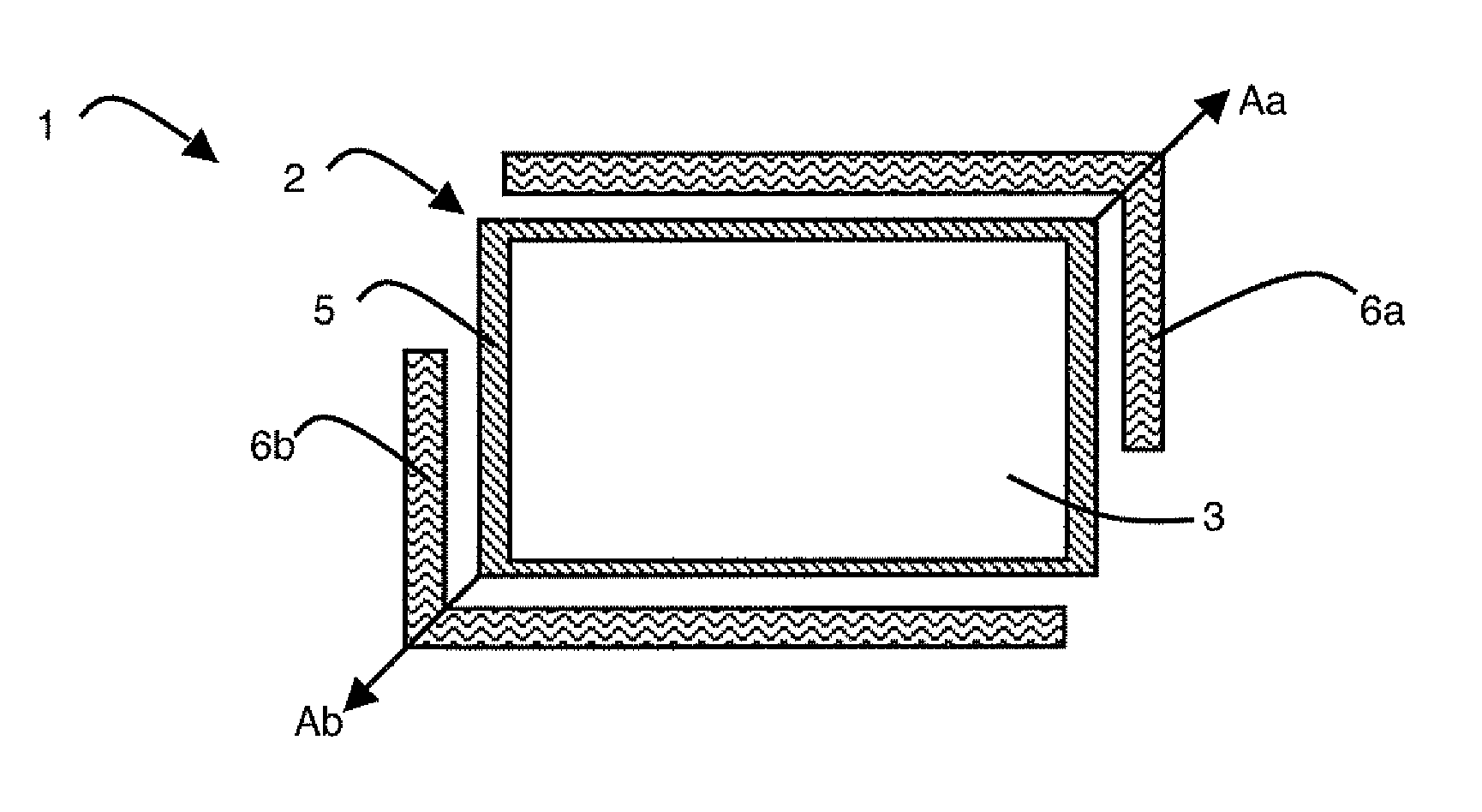
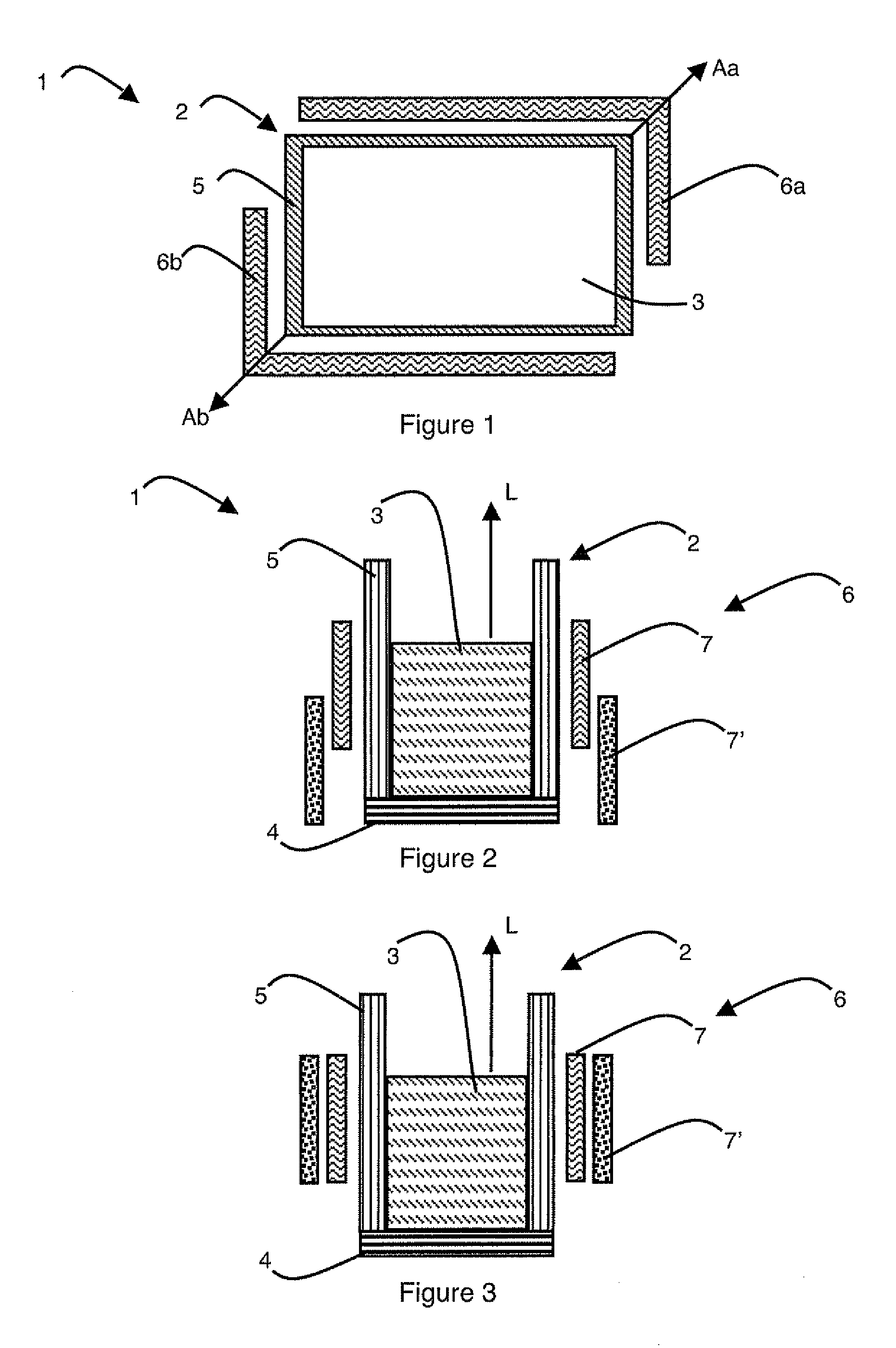
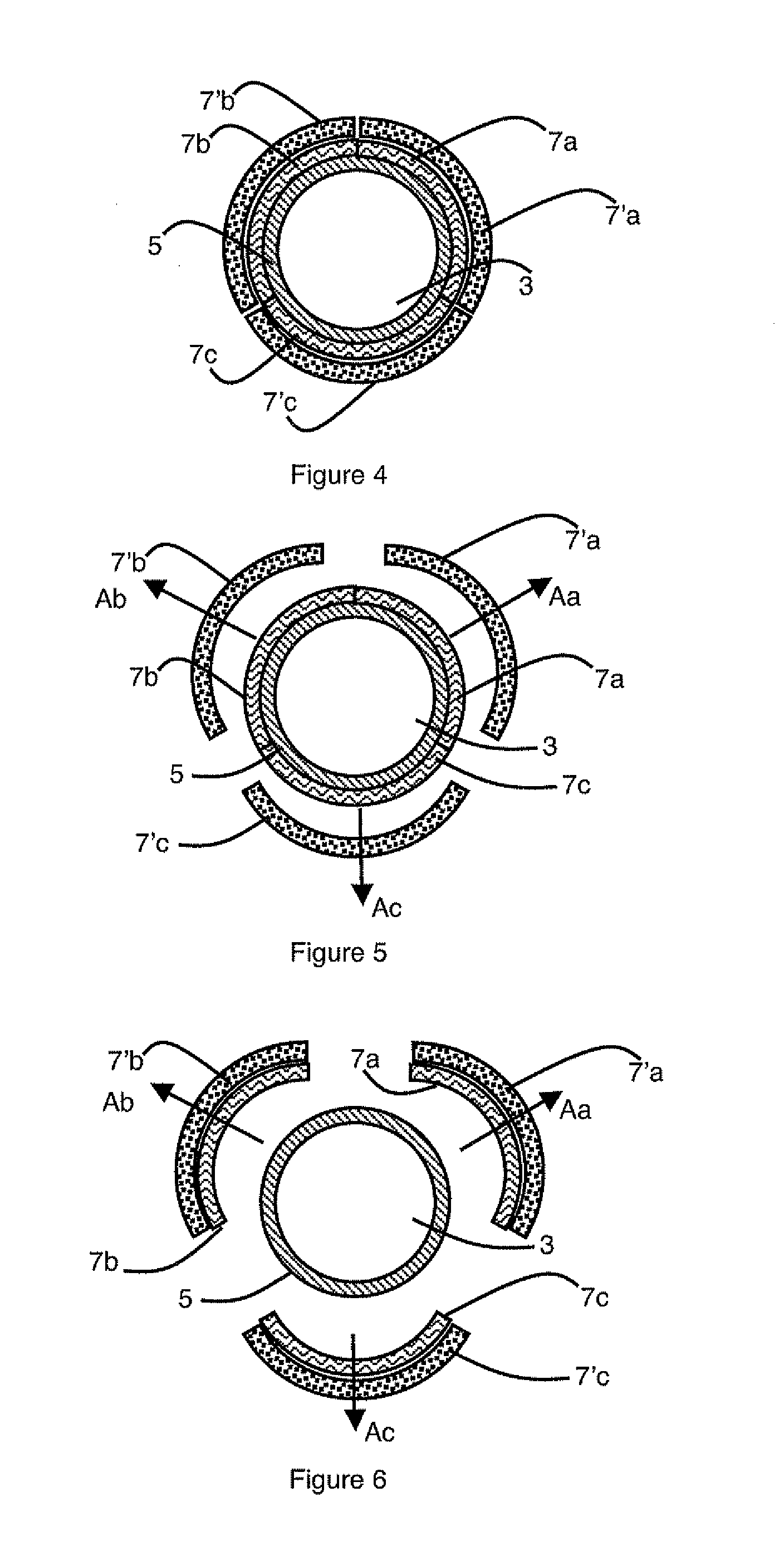
[0023]As illustrated in FIGS. 1 to 6, the melting-solidification furnace 1 comprises a crucible 2 in which a crystalline material 3 of semi-conductor or metal type is placed. Furnace 1 also comprises a heating device of the crystalline material 3 by electromagnetic induction (not shown). The heating device is composed for example of one or more coils inside which an alternating current of predefined frequency flows.

[0024]Crucible 2 has a bottom 4 and side walls 5 made from non-cooled refractory material, the crucible therefore being of hot crucible type. Side walls 5 are oriented in a longitudinal direction L which is perpendicular to bottom 4 of crucible 2. Walls 5 have a height h from bottom 4 of crucible 2 in longitudinal direction L. Crucible 2 presents an outer surface which corresponds to the outer surface of its side walls 5. Crucible 2 is associated with modulating means of the lateral heat leakage. These modulating means enable the proportion of thermal energy leaving cruci...


PUM


Abstract

The melting and solidification furnace for crystalline material includes a crucible having a bottom and side walls, and means for heating the crystalline material by magnetic induction. The furnace includes at least one lateral thermal insulation system arranged at the periphery of the crucible around the side walls. At least one lateral element of the lateral thermal insulation system moves with respect to the side walls between an insulating position and a position fostering thermal leakage. The lateral thermal insulation system has an electric conductivity of less than 1 S/m and a thermal conductivity of less than 15 W/m/K.

Description

BACKGROUND OF THE INVENTION[0001]The invention relates to a melting and solidification furnace for crystalline material comprising:[0002]a crucible having a bottom and side walls,[0003]a lateral thermal insulation system arranged at the periphery of the crucible around the side walls,[0004]means for moving at least one lateral element of the lateral thermal insulation system with respect to the side walls between an insulating position and a position fostering thermal leakage.STATE OF THE ART[0005]In conventional manner, crystalline materials, typically semi-conductor materials and metal materials, cannot be used as such in the different technological fields on account of an insufficient purity and / or an unsuitable crystalline structure. For crystalline materials to be able to comply with very stringent requirement specifications, they are subjected to different melting-solidification cycles in order for example to reduce the quantity of impurities in the material and / or to impose a...

Claims


Application Information

Patent Timeline
IPC IPC(8): F24C15/00
CPCC30B35/002C30B11/003C30B33/02
Inventor PELLETIER, DAVIDGARANDET, JEAN-PAUL
Owner COMMISSARIAT A LENERGIE ATOMIQUE ET AUX ENERGIES ALTERNATIVES
Why Eureka
Try Eureka