
Permanent cathode

Active Publication Date: 2011-10-27
OUTOTEC OYJ
View PDF4 Cites 1 Cited by
  • Summary
  • Abstract
  • Description
  • Claims
  • Application Information

AI Technical Summary

Benefits of technology

[0013]The structure of the edge of the permanent cathode mother plate according to the invention ensures the adhesion of the cathode metal halves, such as cathode copper halves, to each other when stripping the cathodes.
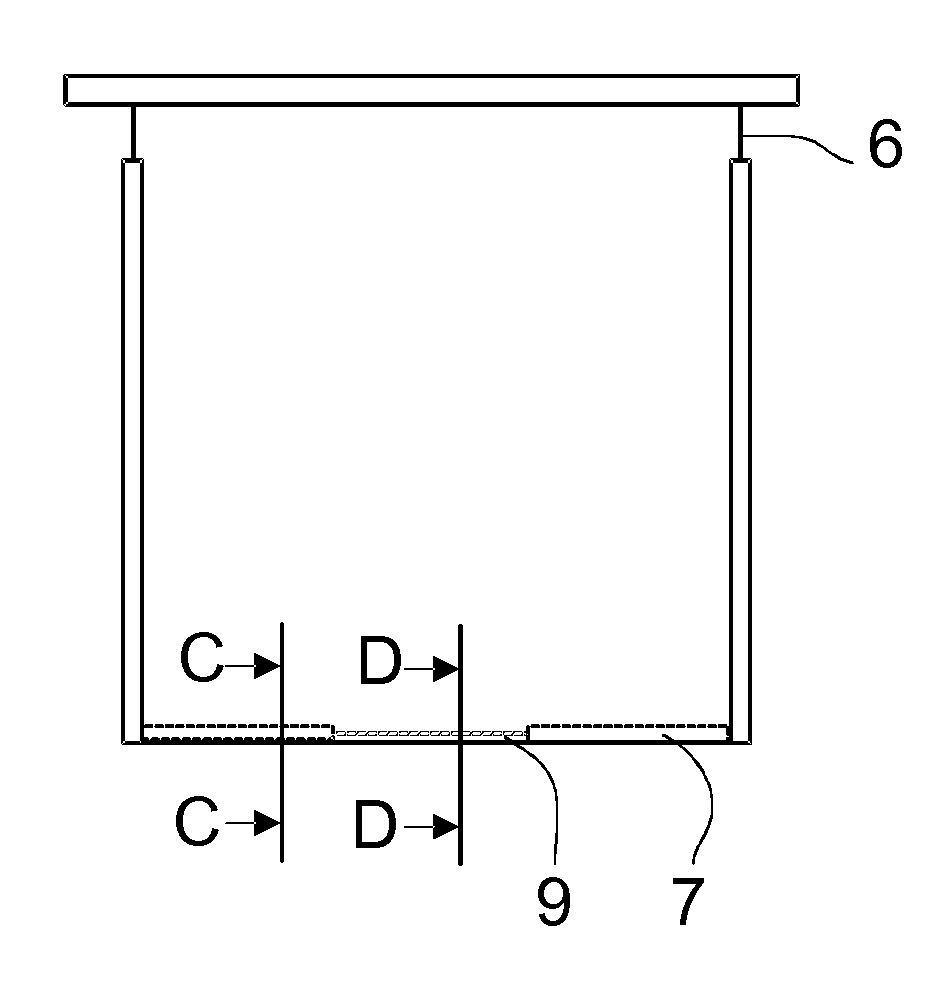
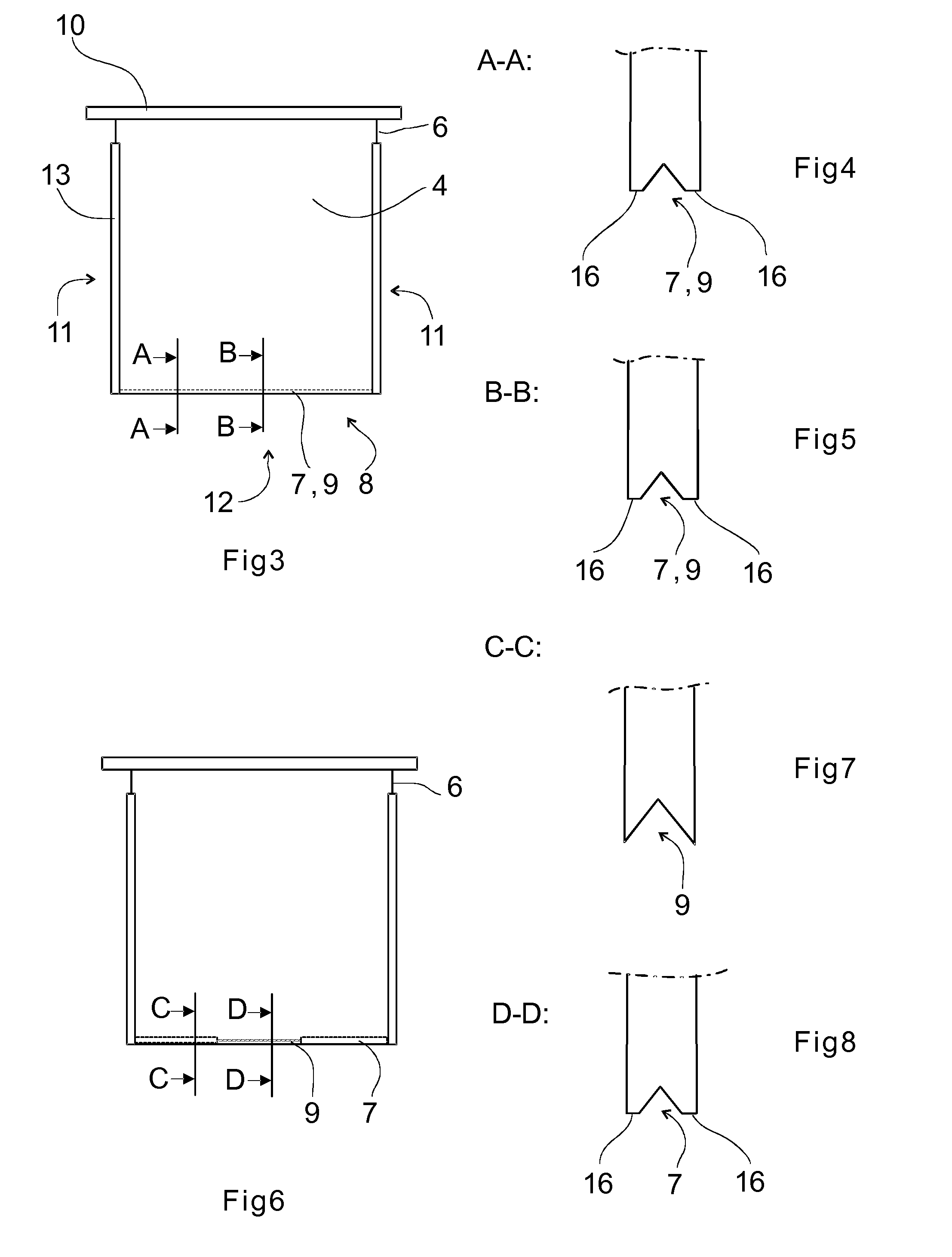
[0014]In a preferred embodiment of the permanent cathode according to the invention, the edge of the permanent cathode mother plate comprises two essentially parallel side edges and a bottom edge. In this preferred embodiment, a groove portion is formed on the bottom edge and the groove portion comprises at least one V groove and at least one flat portion that provides a bridging section between the sides of the mother plate. Such a structure combines the best properties of both the V groove and the flat bottom edge, so that the V groove ensures an easy stripping of the cathode metal and the straight portion ensures the adhesion of the cathode metal halves, such as cathode copper halves, to each other (a “hinge”). For example, at least one V groove is cut in the main part of the mother plate bottom edge but, e.g., a straight bottom edge or a corresponding bridging section is left to extend over an adequately long distance. For example, the straight bottom edge can comprise one section in the middle of the mother plate bottom edge and the length of the straight bottom edge may be about 5-about 50 cm, more preferably about 10-about 40 cm, most preferably about 20-about 30 cm, or it may consist of several short sections. In addition to the adhesion of the cathode metal halves, such as cathode copper halves, one advantage of the structure is that the short straight section does not cause a crease / bag in the lower part of the cathode metal halves, such as cathode copper halves. In that case, the separate pressing straight or straightening of the cathode metal, such as cathode copper, is not needed.

Problems solved by technology

However, the wax used in the method may cause problems both in the electrolysis process and the quality of the cathode metal.
Some also consider the light weight of the cathode metal halves to be a problem, as it influences the casting capacity of the foundry in foundries, where the cathodes are fed into the melting furnace one by one.
If the bottom edge of the permanent cathode plate is completely flat, problems may arise when stripping the metal, as the metal partly gets stuck at the bottom edge of the mother plate.
In the Kidd technology, the V groove furthers the stripping of the cathode metal but may cause the cathode metal halves to break off from each other.
This in turn may be problematic for the user of the cathode.
Consequently, optimizing the depth and the shape of the groove may be quite challenging, as different electrolytic plants have their own preferences regarding the running parameters of the process.

Method used


Image

  • Permanent cathode
  • Permanent cathode
  • Permanent cathode

Examples


Embodiment Construction

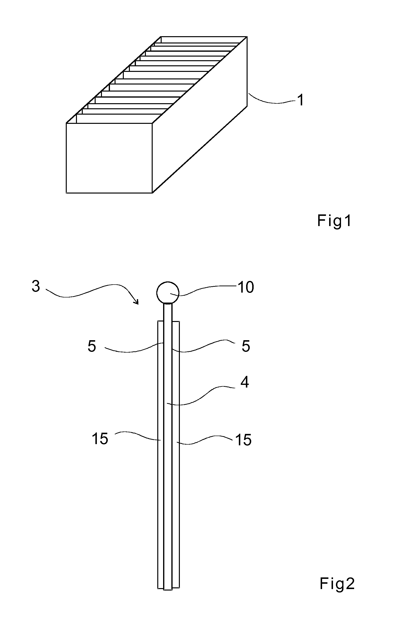
[0043]FIG. 1 shows the electrolytic tank 1, which is used in the electro-refining and / or recovery of metals, such as copper, nickel, cobalt or zinc. In the electrolytic tank 1 shown in FIG. 1, anodes 2 and permanent cathodes 3 are placed alternately. In case of electro-refining copper, the anodes 2 would consist of what is called anode copper and the cathodes would be the permanent cathodes 3 mentioned above, onto the mother plate of which the so-called cathode copper would be reduced in the electrolytic process.

[0044]The figures show the permanent cathode 3 that is to be used as electrode in the electro-refining and / or recovery of metals, such as copper, nickel, cobalt or zinc.

[0045]The permanent cathode 3 comprises a planar mother plate 4 that is made of metal and comprises two sides 5.

[0046]The mother plate 4 comprises an edge 6, which at least partly surrounds the metal plate.

[0047]The edge 6 comprises a groove portion 8 provided with a groove 7.

[0048]The groove portion 8 compri...


PUM

PropertyMeasurementUnit
Lengthaaaaaaaaaa
Lengthaaaaaaaaaa
Lengthaaaaaaaaaa

Abstract

A permanent cathode that is to be used as electrode in the electro-refining and / or recovery of metals, such as copper, zinc, cobalt or nickel. The permanent cathode comprises a planar mother plate that is made of metal and comprises two sides. The mother plate comprises an edge, which at least partly surrounds the metal plate. The edge comprises a groove portion that is provided with a groove. The groove portion comprises at least one bridging section for joining together, over the groove portion of the edge of the metal plate at the at least one bridging section, the cathode metal halves, such as cathode copper halves, cathode zinc halves, cathode cobalt halves or cathode nickel halves, which are formed on the sides of the mother plate in the electro-refining of the metals.

Description

BACKGROUND OF THE INVENTION[0001]The invention relates to a permanent cathode according to the preamble of claim 1 to be used as electrode in the electro-refining and / or recovery of metals, such as copper, zinc, cobalt or nickel.[0002]The invention can be applied, for example, to the electro-refining of copper, wherein anode copper in the form of anodes is transferred onto cathodes by means of an electric current to provide cathode copper. The electro-refining of copper takes place is tanks, in which the anode copper and cathodes are placed by turns and which contain electrolytic liquid. The invention can also be applied, for example, to the electrolytic recovery of copper, nickel, cobalt or zinc.[0003]At present, modern metal electrolyses mainly use what is called a permanent cathode technology, which is based on reducing a metal, such as copper, onto the surface of the mother plate of a permanent cathode made of a suitable steel grade. The metal in the form of a cathode metal half...

Claims


Application Information

Patent Timeline
IPC IPC(8): C25C7/02
CPCC25C7/02
Inventor PALMU, LAURIVIRTANEN, HENRIKIVISTO, TUOMOVIRTANEN, ISMO
Owner OUTOTEC OYJ
Learn More