Small-diameter high bending-resistance fiber optic cable

Inactive Publication Date: 2011-10-27
FITEK PHOTONICS CORPORATION
View PDF1 Cites 6 Cited by
  • Summary
  • Abstract
  • Description
  • Claims
  • Application Information

AI Technical Summary

Benefits of technology

[0010]According to an embodiment of the present invention, the small-diameter high bending-resistance fiber optic cable further includes a sheath strengthening member adapted for fixing the small-diameter high bending-resistance fiber optic cable. The small-diameter high bending-resistance fiber optic cable can be fixed by fixing the sheath strengthening member without fixing the optical transmission unit (e.g., the optical fibers). Therefore, when the small-diameter high bending-resistance fiber optic cable is fixed, the optical transmission unit is avoided from suffering mechanical impact. Alternatively, the sheath strengthening member having very strong mechanical strength instead of the optical transmission unit is fixed. Accordingly, the small-diameter high bending-resistance fiber optic cable can be conveniently deployed in many different sites.
[0011]According to another embodiment of the present invention, the small-diameter high bending-resistance fiber optic cable includes a hollow tube cable structure and an outer protection sheath. The outer p

Problems solved by technology

Even when the conventional soft flexible fiber optic cable has a strengthening layer for strengthening the structure of the fiber optic cable, the rigidity of the aramid yarn material is still less than enough, so that the bending-resistance of the conventional soft flexible fiber optic cables is not satisfactory.
When such a conventional soft flexible fiber optic cable is tigh

Method used


Image

  • Small-diameter high bending-resistance fiber optic cable
  • Small-diameter high bending-resistance fiber optic cable
  • Small-diameter high bending-resistance fiber optic cable

Examples


first embodiment

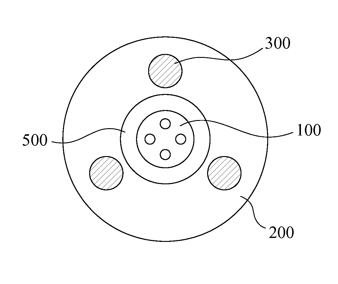
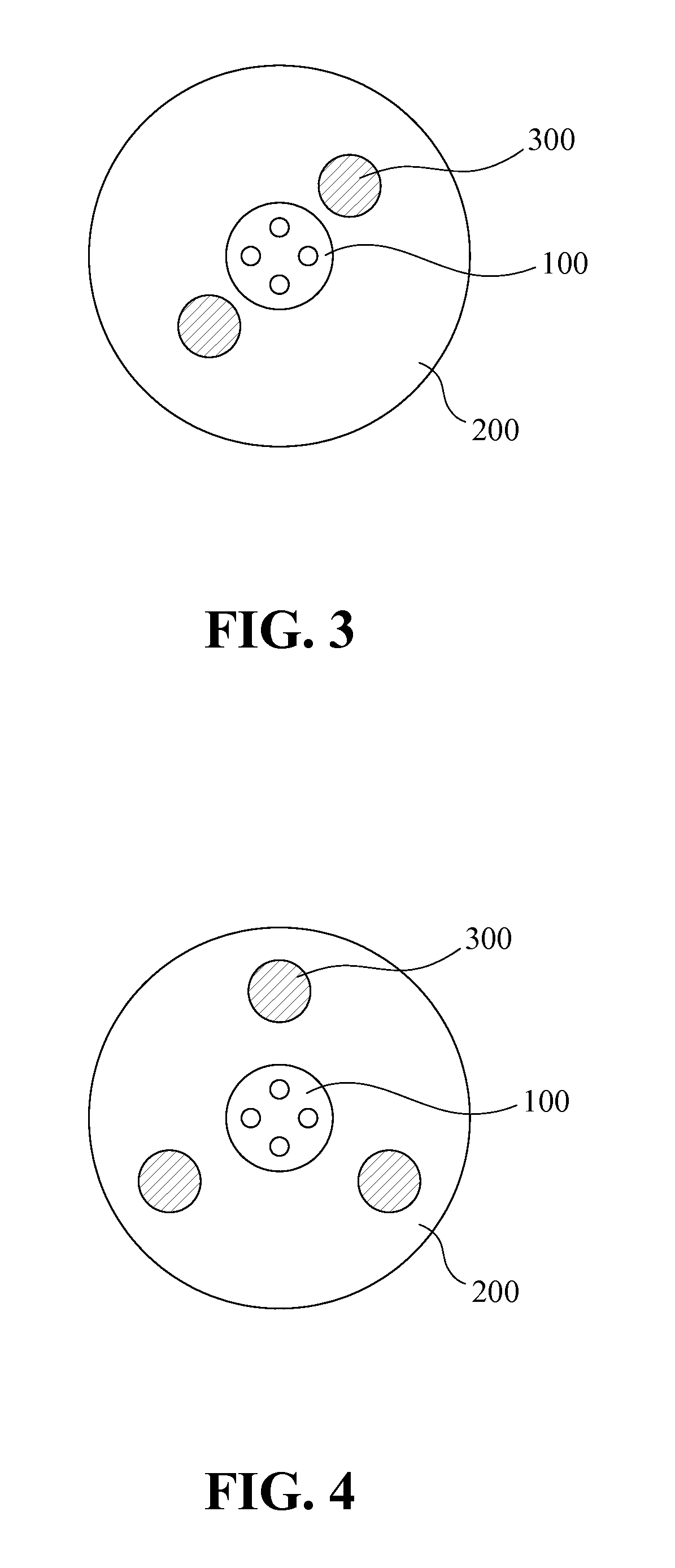
[0024]FIG. 3 is a cross-sectional view of a small-diameter high bending-resistance fiber optic cable according to the present invention. Referring to FIG. 3, there is shown a small-diameter high bending-resistance fiber optic cable. The small-diameter high bending-resistance fiber optic cable has a diameter at least smaller than 6 mm. The small-diameter high bending-resistance fiber optic cable includes an optical communication unit 100, an outer protection sheath 200 and a plurality of tensile-resistance members 300. The optical communication unit 100 is a medium adapted for transmitting optical signals. The optical communication unit 100 includes at least one optical fiber. The optical fiber for example is a coloring fiber, a ribbon fiber, a tight buffer fiber, or any other suitable optical fibers. The outer protection sheath 200 is disposed over the optical communication unit 100. Relatively, the optical communication unit 100 is positioned at a center or other position of the ou...

second embodiment

[0028]FIG. 4 is a cross-sectional view of a small-diameter high bending-resistance fiber optic cable according to the present invention. Referring to FIG. 4, there is shown a small-diameter high bending-resistance fiber optic cable. The small-diameter high bending-resistance fiber optic cable includes an optical communication unit 100 and three tensile-resistance members 300. The optical communication unit 100 includes four optical fibers. Referring to FIGS. 3 and 4 together, it can be learnt that the quantity of the optical fibers of the optical communication unit 100, the quantity of the tensile-resistance members 300, and the distribution thereof can be adaptively modified for satisfying practical requirements. The outer protection sheath 200 together with the associated tensile-resistance members 300 can effectively improve the bending and twisting of the fiber optic cable during the deploying operation.

[0029]FIG. 5 is a cross-sectional view of a small-diameter high bending-resi...

fifth embodiment

[0031]FIG. 7 is a cross-sectional view of a small-diameter high bending-resistance fiber optic cable according to the present invention. Referring to FIG. 7, the small-diameter high bending-resistance fiber optic cable includes a hollow tube cable structure 400, an outer protection sheath 200, and a plurality of tensile-resistance members 300. The small-diameter high bending-resistance fiber optic cable has an outer diameter smaller than 6 mm. The outer protection sheath 200 is disposed over the hollow tube cable structure 400. The tensile-resistance members 300 are disposed inside and extending along the outer protection sheath 200. Preferably, the tensile-resistance members 300 are made of an FRP material. Specifically, the FRP material is selected from the group consisting of GFRP, CFRP, and steel wire. The hollow tube cable structure 400 is adapted for being provided with an optical transmission unit 100 extending there through. In such a way, the present invention provides a sm...


PUM


Abstract

A small-diameter high bending-resistance fiber optic cable adapted for obtaining a high tensile-resistance and a high bending-resistance is provided. The small-diameter high bending-resistance fiber optic cable is particularly adapted for being deployed in indoor pipelines. The small-diameter high bending-resistance fiber optic cable includes at least one optical fiber core, an outer protection sheath, and a plurality of tensile-resistance members. The optical fiber core is positioned in a center of the outer protection sheath. The tensile-resistance members are uniformly distributed in the outer protection sheath. The tensile-resistance members are made of aramid yarn material.

Description

BACKGROUND OF THE INVENTION[0001]1. Field of the Invention[0002]The present invention relates generally to a small-diameter high bending-resistance fiber optic cable. The fiber optic cable includes an outer protection sheath including a tensile-resistance member adapted for improving tensile strength and bending resistance of the fiber optic cable. Such a small-diameter and high bending-resistance fiber optic cable is particularly adapted for indoor cable routing.[0003]2. The Prior Arts[0004]In fiber-to-the-home (FTTH) optical communication network, the fiber optic cables used for accessing the clients or deployed in the horizontal pipelines of the buildings are often soft flexible cables and don't have a high bending-resistance.[0005]Referring to FIG. 1, there is shown a cross-sectional view of a conventional soft flexible fiber optic cable. As shown in FIG. 1, the soft flexible fiber optic cable includes a single-core fiber 1 and an outer protection sheath 2. The outer protection ...

Claims


Application Information

Patent Timeline
IPC IPC(8): G02B6/44
CPCG02B6/4433
Inventor HSU, KUANG-BANG
Owner FITEK PHOTONICS CORPORATION
Why Eureka
Try Eureka