
Discreetly Defined Porous Wall Structure for Transpirational Cooling

a porous wall and discretely defined technology, applied in the direction of engine manufacturing, additive manufacturing apparatus, thin material processing, etc., can solve the problems of reducing the efficiency of the machine, randomly porous materials are generally not suitable, fibrous structures are not inherently geometrically rigid,

Active Publication Date: 2011-10-27
MIKRO SYSYTEMS INC +1
View PDF15 Cites 65 Cited by
  • Summary
  • Abstract
  • Description
  • Claims
  • Application Information

AI Technical Summary

Problems solved by technology

This air bypasses the combustion chamber, reducing the efficiency of the machine.
Randomly porous materials are generally not be suitable for high temperature, high load-bearing structures because they have random anisotropies due to uneven distributions of voids and solids that can cause weak points and uneven cooling.
In addition, random fibrous structures are not inherently geometrically rigid.

Method used


Image

  • Discreetly Defined Porous Wall Structure for Transpirational Cooling
  • Discreetly Defined Porous Wall Structure for Transpirational Cooling
  • Discreetly Defined Porous Wall Structure for Transpirational Cooling

Examples


embodiment 70

[0018]FIG. 5 shows a 3-D lattice embodiment 70 of the invention, composed of nodes 72 and links 74. It may have geometry like that of a crystal lattice model, and may have a scale of 0.1-5.0 mm spacing per unit cell in one embodiment (a node and its directly attached links). This forms a meta-material with characteristics determined by the lattice geometry, scale, and thicknesses of the nodes and links. Rigidity can be controlled in part by the lattice geometry. For example, in FIG. 5 rigidity and flow restriction can be increased by adding vertical links between nodes lacking them (exemplified by nodes 76, 77, 78) and / or by adding horizontal links between nodes lacking them (exemplified by nodes 77 and 79) and / or by adding additional nodes such as halfway between nodes 77 and 79. Such additional vertical links, horizontal links and additional nodes will impact rigidity and flow restriction in the respective directions to a different degree, thereby providing the designer with flexi...

embodiment 80

[0019]FIG. 6 shows an embodiment 80 formed by layers of waffle structures D, E. Each layer D and E has opposed open-ended cells 82, especially rectangular cells. Square cells are shown. Each cell has a bottom wall 84, which may or may not have a pass-through hole 86. Two adjacent layers D and E may have the same geometry. They may be offset from each other vertically or diagonally by up to half a cell spacing. In FIG. 6, the layers D and E are offset from each other by half a cell diagonal length 88. Using this offset, adjacent layers D, E contact and connect to each other only at crossing areas 83 on each side wall of each cell. These crossing areas 83 may be enlarged relative to a thickness of the cell side wall as shown.

[0020]This vertical and / or diagonal offset allows air to flow both vertically and horizontally between the overlapping voids of the cells 82. Three exemplary flow paths 38-38A, 38-38B, and 38-38C are shown. An air flow 38 enters through inlets in the layer in fron...


PUM


Abstract

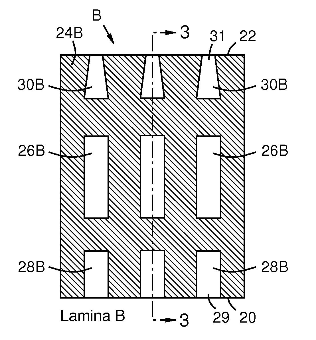
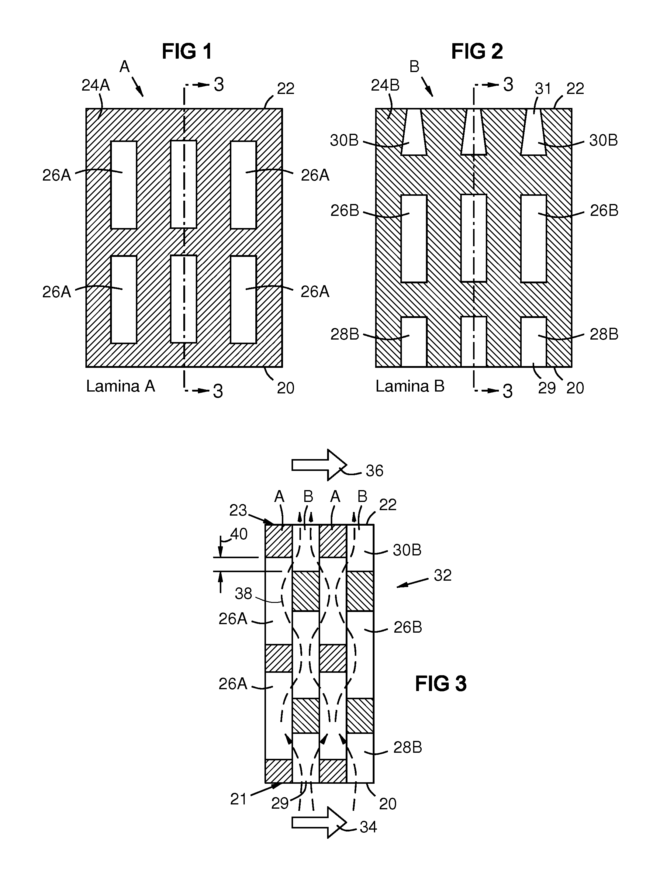
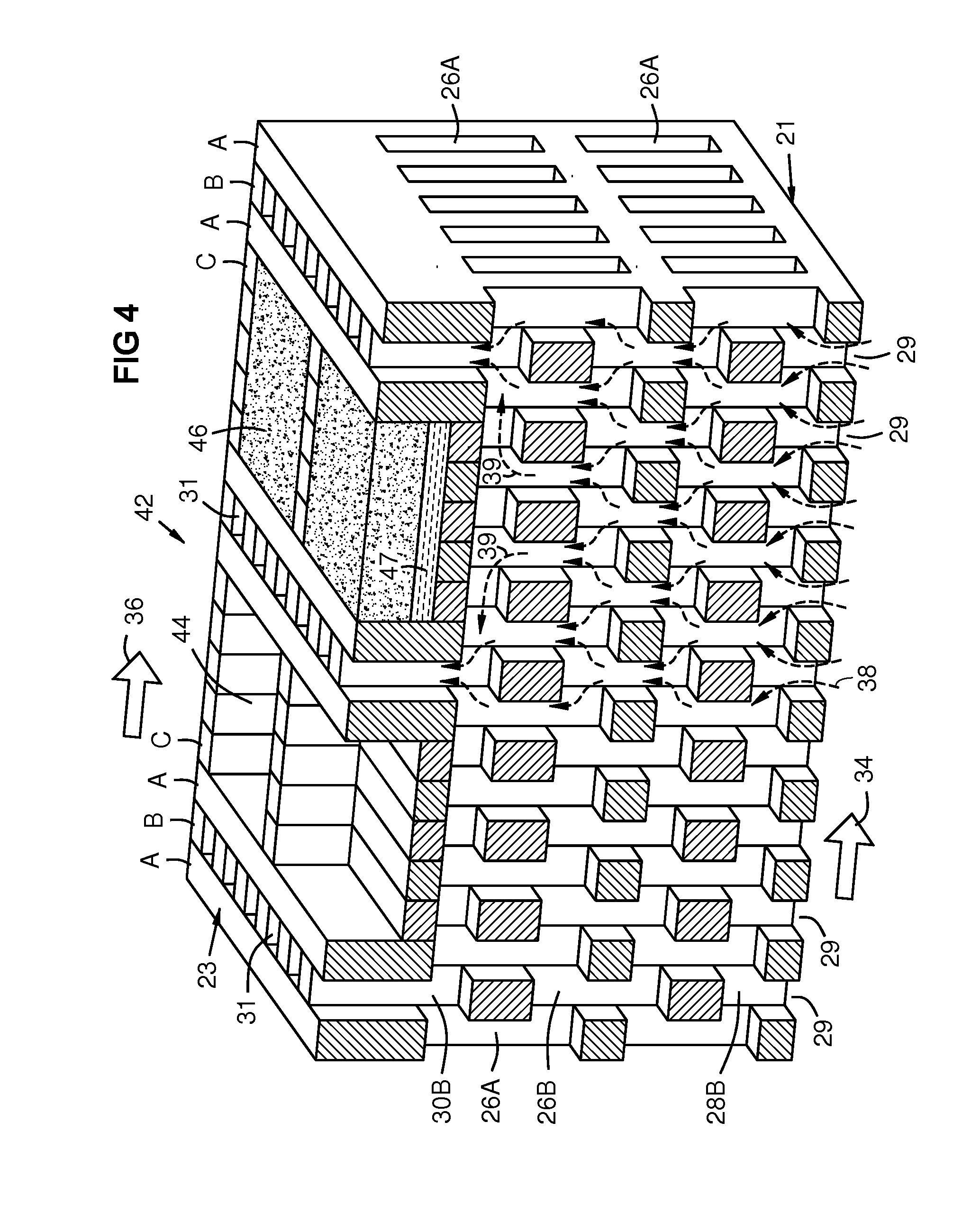
A wall structure (32, 42, 68, 70, 80) with layers (A, B, C, D, E) of non-random voids (26A, 26B, 28B, 30B) that interconnect to form discretely defined tortuous passages between an interior (21) and an exterior surface (23) of the wall for transpiration cooling of the wall. A coolant flow (38) through the wall may be metered by restrictions in coolant outlets (31) and / or within the passages to minimize the coolant requirement. Pockets (44) may be formed on the exterior surface of the wall for thermal Insulation (46). The layers may be formed by lamination, additive manufacturing, or casting. Layer geometries include alternating layers (A, B, C) with different overlapping void patterns (42), 3-D lattice structures (70), and offset waffle structures (80).

Description

FIELD OF THE INVENTION[0001]This invention relates to through-wall fluid cooling of wall structures, and particularly to transpiration cooling of components in gas turbine engines.BACKGROUND OF THE INVENTION[0002]In a gas turbine engine, hot section components, such as combustor liners, transition ducts, turbine airfoils, and turbine rings, require cooling airflows which are typically drawn from the high-pressure compressor. This air bypasses the combustion chamber, reducing the efficiency of the machine. There is a long-standing need for cooling schemes that require the use of less cooling air for improved engine efficiency and emission control.[0003]Impingement and convection cooling have been used on interior surfaces of component walls (backside cooling). Film cooling has been used on exterior surfaces exposed to the hot combustion gas to cool the boundary layer of hot gas flow. Exterior surfaces may have thermal barrier coatings (TBC) for thermal insulation. Component walls are...

Claims


Application Information

Patent Timeline
IPC IPC(8): B32B3/10
CPCF01D5/182F01D5/183F01D5/184F05D2250/185F05D2250/28Y10T428/24273F05D2230/22F05D2250/30F05D2260/221F05D2260/203F05D2230/90F05D2250/18B33Y80/00
Inventor LEE, CHING-PANGPRAKASH, CHANDERMERRILL, GARY B.HESELHAUS, ANDREASBURNS, ANDREW J.
Owner MIKRO SYSYTEMS INC
Learn More