Encoding method, encoder and decoder

Active Publication Date: 2011-10-27
PANASONIC INTELLECTUAL PROPERTY CORP OF AMERICA
View PDF4 Cites 17 Cited by
  • Summary
  • Abstract
  • Description
  • Claims
  • Application Information

AI Technical Summary

Benefits of technology

[0085]According to the present invention, it is possible to change a coding rate of an erasure correction code while reducing the circuit scales of an encoder and decoder, and thereby realize both improvement of transmission efficiency and improvement of erasure correction capability.

Problems solved by technology

However, when a number of packets beyond the correction capability of the Reed-Solomon code are lost, or packets are continuously lost due to fading or the like in a wireless communication channel over a relatively long period of time and burst erasure occurs, erasure correction may not be effectively performed.
When the Reed-Solomon code is used, although the correction capability can be improved by increasing the block length of the Reed-Solomon code, there is a problem that the amount of computation of coding / decoding processing and the circuit scale will increase.
Due to this bit error, a packet including the corresponding bit cannot be correctly decoded in the upper layer and packet erasure may result.

Method used


Image

  • Encoding method, encoder and decoder
  • Encoding method, encoder and decoder
  • Encoding method, encoder and decoder

Examples


embodiment 1

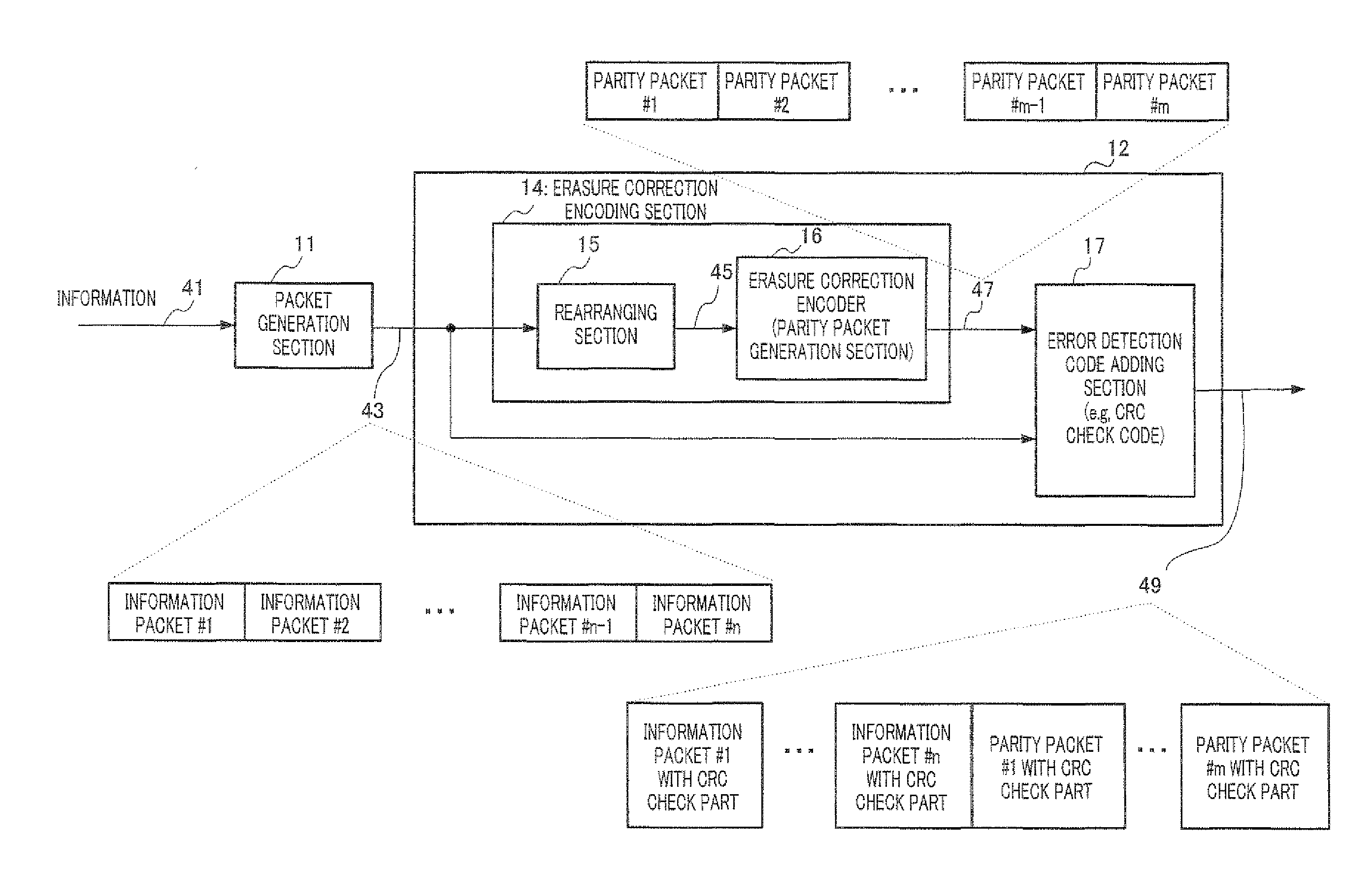
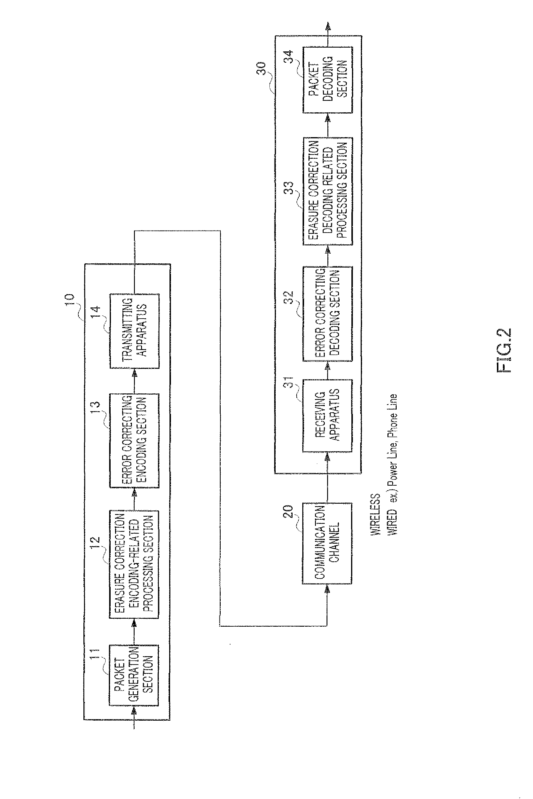
[0127]FIG. 6 is an overall configuration diagram of a communication system according to Embodiment 1 of the present invention. In FIG. 6, the communication system includes communication apparatus 100 on an encoding side communication channel 20, and communication apparatus 200 on a decoding side. Communication channel 20 represents a path through which a signal transmitted from transmitting apparatus 140 of communication apparatus 100 on the encoding side passes until it is received by receiving apparatus 210 of communication apparatus 200 on the decoding side. The communication system in FIG. 6 differs from the communication system in FIG. 2 in that the communication system in FIG. 6 can change the coding rate of an erasure correction code.

[0128]Receiving apparatus 210 of communication apparatus 200 receives a signal transmitted from communication apparatus 100 and estimates a communication state from control information signals such as pilot signals a id preambles of the received ...

embodiment 2

[0182]Embodiment 1 has described the method of making the coding rate of an erasure correction code variable. A case will be described below where the method of making the coding rate of the erasure correction code variable described in Embodiment 1 will be realized using an LDPC-CC (e.g. see Non-Patent Literature 3).

[0183]As a premise thereof, the present embodiment will describe an LDPC-CC having good characteristics first. Embodiment 3 will describe a method of making the coding rate variable when an LDPC-CC is applied to a physical layer which will be described in the present embodiment. Embodiment 4 will describe a method of making the coding rate variable when the LDPC-CC described in the present embodiment is used for an erasure correction code.

[0184]An LDPC-CC is a convolutional code defined by a low-density parity check matrix. As an example, FIG. 14 illustrates parity check matrix HT[0,n] of an LDPC-CC of a coding rate of R=½. Here, element h1(m)(t) of HT[0,n] has a value ...

embodiment 3

[0390]Embodiment 2 has described an LDPC-CC having good characteristics.

[0391]The present embodiment will describe a shortening method that makes a coding rate variable when the LDPC-CC described in Embodiment 2 is applied to a physical layer. “Shortening” refers to generating a code of a second coding rate from a code of a first coding rate (first coding rate>second coding rate). Hereinafter, a shortening method of generating an LDPC-CC of a coding rate of ⅓ from an LDPC-CC of a coding rate of ½ will be described as an example.

[0392]FIG. 23 shows an example of check equations of an LDPC-CC of a coding rate of ½ and parity check matrix H. The LDPC-CC of a coding rate of ½ shown in FIG. 23 is an example of the LDPC-CC of a time varying period of 3 having good characteristics described in Embodiment 1 and parity check matrix H is made up of equations 27-1 to equation 27-3.

[27]

(Da1+Da2+Da3)X(D)+(Db1+Db2+Db3)P(D)=(D2+D1+1)X(D)+(D2+D1+1)P(D)=0  (Equation 27-1)

(DA1+DA2+DA3)X(D)+(DB1+DB2+D...


PUM


Abstract

Disclosed is an encoding method to change an encoding rate of an erasure correcting code, while decreasing a circuit scale of an encoder and a decoder. 12k bit (wherein k represents a natural number) which is an encoding output using LDPC-CC with an encoding rate of ½, and comprises information and parity, is defined as one cycle. From the one cycle, only the information is arranged in the output order of the encoding output to obtain 6k bit information X6i, X6i+1, X6i+2, X6i+3, X6i+4, X6i+5, . . . , X6(i+k−1) X6(i+k−1)+1, X6(i+k−1)+2, X6(i+k−1)+3, X6(i+k−1)+4, and X6(i+k−1)+5. Known information is inserted, in 3k pieces of information (Xj) among the 6k bit information, so that when 3k pieces of mutually different j is divided by 3, there is a remainder of 0 regarding k pieces, there is a remainder of 1 regarding k pieces, and there is a remainder of 2 regarding k pieces, to thereby obtain the parity from the information containing the known information.[Numerical formulas](Da1+Da2+Da3)X(D)+(Db1+Db2+Db3)P(D)=0  (1-1)(DA1+DA2+DA3)X(D)+(DB1+DB2+DB3)P(D)=0  (1-2)(Da1+Da2+Da3)X(D)+(Dss1+Dss2+Dss3)P(D)=0  (1-3)wherein X(D) is a polynomial expression of the information X; P(D) is a polynomial expression of the parity; a1, a2, a3 are integers (with the proviso that a1≠a2≠a3); b1, b2, b3 are integers (with the proviso that b1≠b2≠b3); A1, A2, A3 are integers (with the proviso that A1≠A2≠A3); B1, B2, B3 are integers (with the proviso that B1≠B2≠B3); a1, a2, a3 are integers (with the proviso that a1≠a2≠a3); ss1, ss2, ss3 are integers (with the proviso that ss1≠ss2≠ss3); and “c % d” represents “a remainder when c is divided by d”.

Description

TECHNICAL FIELD[0001]The present invention relates to an encoding method, an encoder and a decoder that perform erasure correction encoding using, for example, low density parity check codes (LDPC Codes).BACKGROUND ART[0002]For application such as moving image streaming, when more than a tolerable number of packets are lost at an application level, error correction codes are used to secure quality. For example, Patent Literature 1 discloses a method of creating redundant packets for a plurality of information packets using a Reed-Solomon code and transmitting the information packets with the redundant packets attached thereto. By so doing, even when packets are lost, the erased packets can be decoded as long as the loss is within the range of error correction capability of the Reed-Solomon code.[0003]However, when a number of packets beyond the correction capability of the Reed-Solomon code are lost, or packets are continuously lost due to fading or the like in a wireless communicat...

Claims


Application Information

Patent Timeline
IPC IPC(8): H03M13/05G06F11/10
CPCH03M13/1102H03M13/23H03M13/235H04L1/0041H03M13/6502H03M13/6516H03M13/353H03M13/2792
Inventor MURAKAMI, YUTAKA
Owner PANASONIC INTELLECTUAL PROPERTY CORP OF AMERICA
Why Eureka
Try Eureka