Solar Powered Umbrella Table

a solar energy and umbrella technology, applied in the field of umbrella tables, can solve the problems of cords not reaching the external power source, external power sources may also be impossible to use, and objects' cords cannot reach the external power sour

a solar energy and umbrella technology, applied in the field of umbrella tables, can solve the problems of cords not reaching the external power source, external power sources may also be impossible to use, and objects' cords cannot reach the external power sour

US20110265694A1Inactive Publication Date: 2011-11-03PORTIS JR MATTHEW N +1

Image

  • Solar Powered Umbrella Table
  • Solar Powered Umbrella Table
  • Solar Powered Umbrella Table

Examples


Embodiment Construction

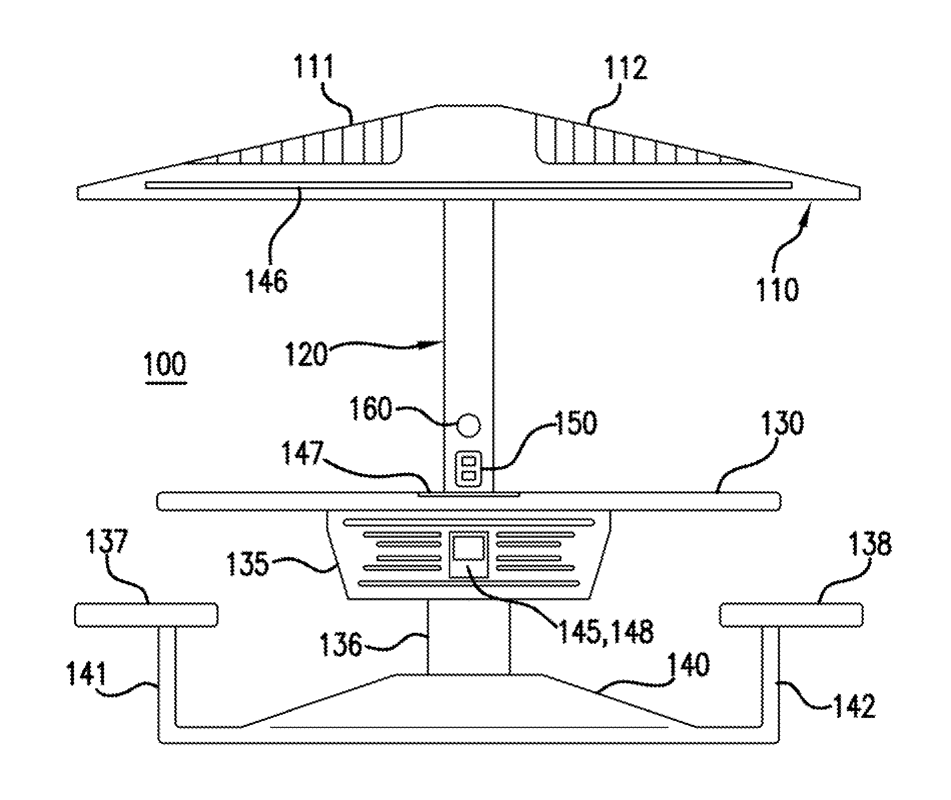
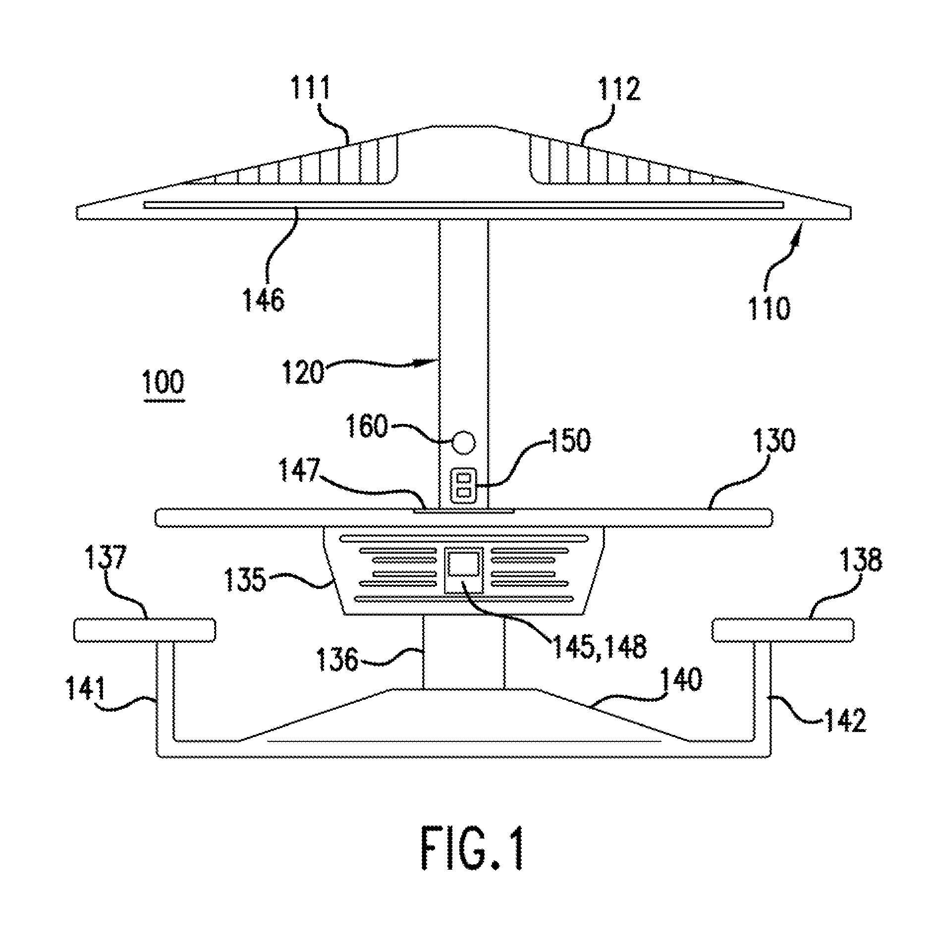
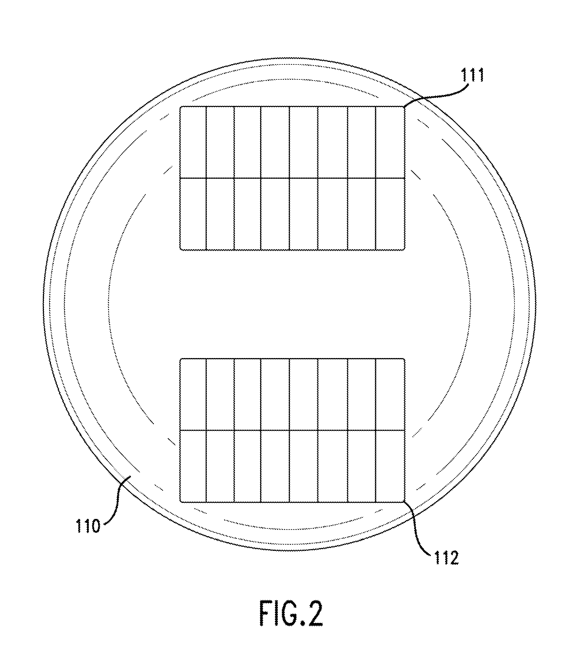
[0012]Referring to the figures, FIG. 1 is a perspective view of the table and umbrella apparatus 100. The apparatus 100 comprises an umbrella 110 having at least one solar energy collection device 111, 112 that converts solar energy to an electrical DC voltage. The umbrella is preferably a fiber glass material. However, various types of materials may be used so long as they are strong enough to support the panels 111, 112 and so long as the panels 111,112 are not able to cut through the material. An aspect of an embodiment of the invention features solar panels as the solar energy collection devices. Two solar panels 111, 112 are shown in FIG. 1 and FIG. 2, however it is understood that additional solar panels can be used or that one solar panel can be used to collect solar energy. FIG. 2 is a top view of the umbrella 110. The solar panels 111, 112 are spaced and positioned for the optimal exposure to the sun. The solar panels are groups of solar cells in the form of a panel designe...


PUM


Abstract

A solar umbrella and table apparatus with attached chairs features stand-alone AC power, generated from solar energy. The apparatus features an umbrella having solar collection devices and a table with attached seating chairs. The electrical system of the apparatus converts collected solar energy to an electrical voltage. Batteries store the energy provided by the solar panels. Inverters convert the DC voltage output from the storage batteries to 120 volts AC. Power outlet terminals are located on the umbrella and table apparatus allow 120 volts AC powered devices to access the output of the sine wave power inverters.

Description

FIELD OF THE INVENTION[0001]The present invention relates in general to a table having an umbrella with an integrated solar power supply.BACKGROUND OF THE INVENTION[0002]Tables with umbrellas are commonly used for outdoor entertaining and dining. Objects are placed on the tables that require a power source. However, external power sources present a problem because having cords run from the table to the external power source take up unnecessary space and the cords create a safety hazard. Also, if the tables are placed too far from the external power source, the object's cord will not reach the external power source. The external power source may also be impossible to use because of its remote location making it not readily accessible. During nighttime hours, it is difficult to see the external power source.[0003]Owners of tables with umbrellas shy away from allowing users to use their external power source due to the problems discussed and added liability. Also, owners are not willin...

Claims


Application Information

Patent Timeline
03 Nov 2011
Publication
US20110265694A1
IPC
A47B37/00; G01N5/02; H01M10/46; A45B3/00; H02J7/00
CPC
A45B3/00; A45B2200/1027; H02J7/355; A47B37/04; H01M10/465; A45B2200/1063; H02J7/35; Y02E60/10
Inventors
PORTIS, MATTHEW; HAMPTON, OBADIAH