
Apparatus and Methods for Detecting Performance Data in an Earth-Boring Drilling Tool

a technology of performance data and equipment, applied in earth-moving drilling, surveying, borehole/well accessories, etc., can solve the problems of affecting drilling operations, affecting drilling operations, and relatively infrequent failures,

Active Publication Date: 2011-11-03
BAKER HUGHES INC
View PDF21 Cites 72 Cited by
  • Summary
  • Abstract
  • Description
  • Claims
  • Application Information

AI Technical Summary

Benefits of technology

In one embodiment, a cutting element of an earth-boring drilling tool is disclosed. The cutting element comprises a substrate with a cutting surface thereon, at least one thermistor sensor coupled with the cutting surface, and a conductive pathway operably coupled with the

Problems solved by technology

The oil and gas industry expends sizable sums to design cutting tools, such as downhole drill bits including roller cone rock bits and fixed cutter bits, which have relatively long service lives, with relatively infrequent failure.
The loss of a roller cone or a polycrystalline diamond compact (PDC) from a fixed cutter bit during drilling operations can impede the drilling operations and, at worst, necessitate rather expensive fishing operations.
The drilled portions through the substrate and diamond table for housing the thermocouples may compromise the mechanical strength of the cutter.
Thermocouples may also require the use of relatively large voltage drivers, which may limit the downhole usefulness in obtaining accurate and representative temperature measurements during actual rock cutting during a subterranean drilling operation or, at the least, in a drilling simulator.
As a result of these and other issues, conventional thermal measurements have been limited to laboratory experiments rather than obtaining real-time performance data during rock cutting.

Method used


Image

  • Apparatus and Methods for Detecting Performance Data in an Earth-Boring Drilling Tool
  • Apparatus and Methods for Detecting Performance Data in an Earth-Boring Drilling Tool
  • Apparatus and Methods for Detecting Performance Data in an Earth-Boring Drilling Tool

Examples


Embodiment Construction

The illustrations presented herein are not meant to be actual views of any particular material, apparatus, system, or method, but are merely idealized representations which are employed to describe the present disclosure. Additionally, elements common between figures may have a similar numerical designation.

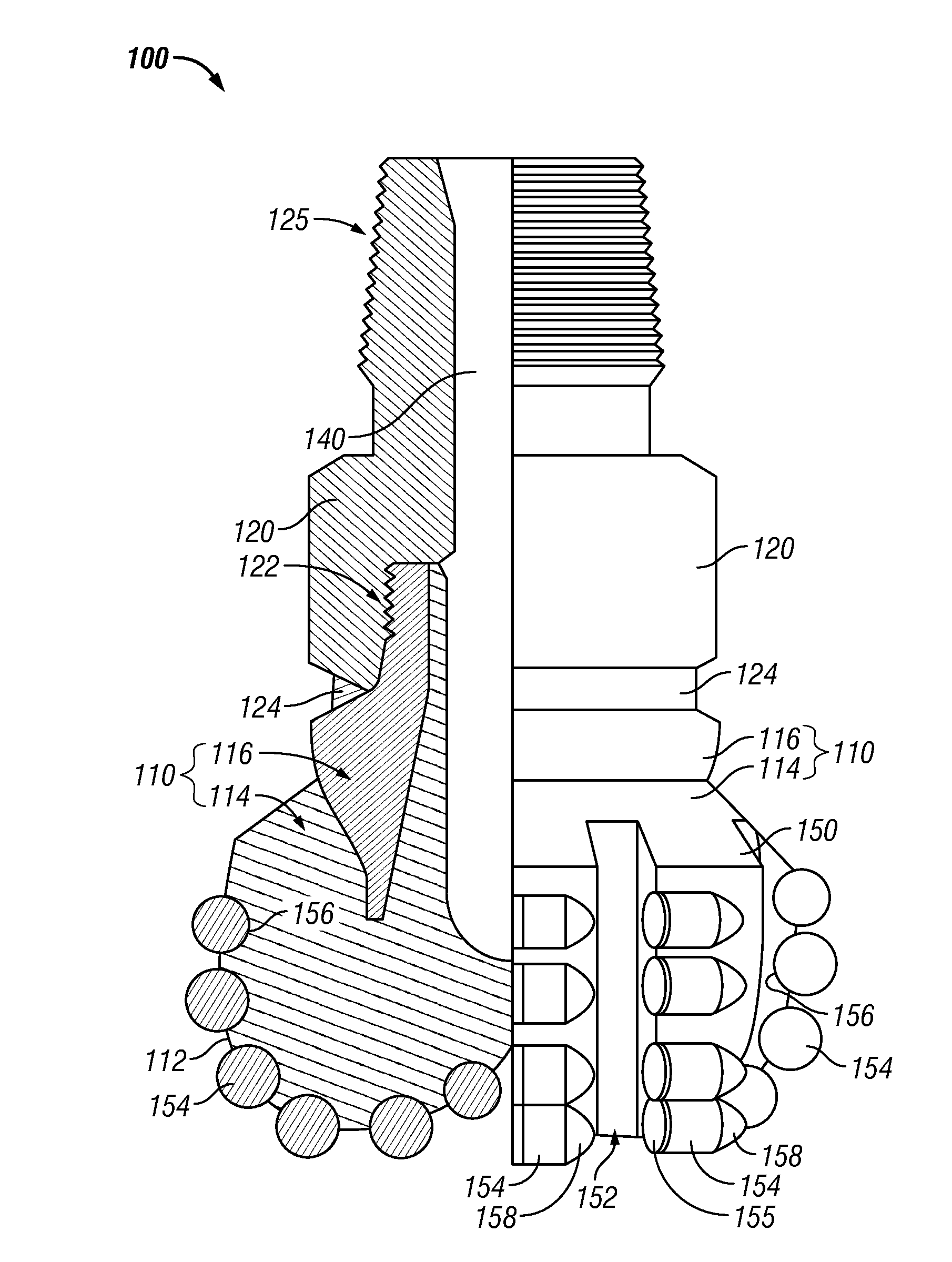
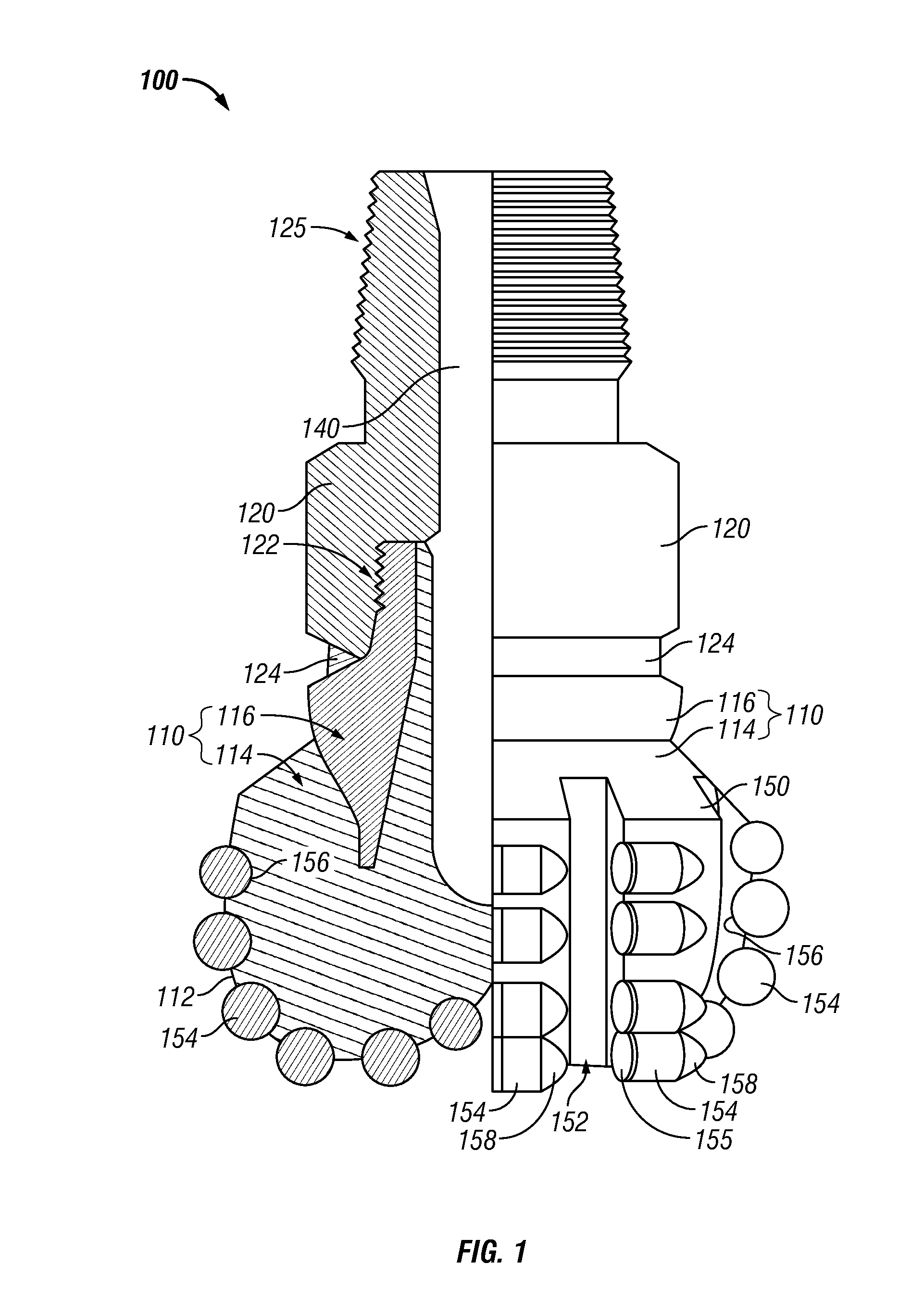
As used herein, a “drill bit” means and includes any type of bit or tool used for drilling during the formation or enlargement of a wellbore in subterranean formations and includes, for example, fixed cutter bits, rotary drill bits, percussion bits, core bits, eccentric bits, bi-center bits, reamers, mills, drag bits, roller cone bits, hybrid bits and other drilling bits and tools known in the art.

As used herein, the term “polycrystalline material” means and includes any material comprising a plurality of grains or crystals of the material that are bonded directly together by inter-granular bonds. The crystal structures of the individual grains of the material may be randomly ori...


PUM

PropertyMeasurementUnit
Temperatureaaaaaaaaaa
Electrical resistanceaaaaaaaaaa
Electrical conductoraaaaaaaaaa

Abstract

Methods and associated tools and components related to generating and obtaining performance data during drilling operations of a subterranean formation is disclosed. Performance data may include thermal and mechanical information related to earth-boring drilling tool during a drilling operation are disclosed. For example, a cutting element of an earth-boring drilling tool may include a substrate with a cutting surface thereon. The cutting element may further include at least one thermistor sensor coupled with the cutting surface, and a conductive pathway operably coupled with the at least one thermistor sensor. The at least one thermistor sensor may be configured to vary a resistance in response to a change in temperature. The conductive pathway may be configured to provide a current path through the at least one thermistor sensor in response to a voltage. Other methods, tools and components are provided.

Description

BACKGROUND OF THE DISCLOSUREField of the DisclosureThe present disclosure generally relates to earth-boring drill bits, cutting elements attached thereto, and other tools that may be used to drill subterranean formations. More particularly, embodiments of the present disclosure relate to obtaining diagnostic measurements of components of an earth-boring drill bit.BACKGROUNDThe oil and gas industry expends sizable sums to design cutting tools, such as downhole drill bits including roller cone rock bits and fixed cutter bits, which have relatively long service lives, with relatively infrequent failure. In particular, considerable sums are expended to design and manufacture roller cone rock bits and fixed cutter bits in a manner that minimizes the opportunity for catastrophic drill bit failure during drilling operations. The loss of a roller cone or a polycrystalline diamond compact (PDC) from a fixed cutter bit during drilling operations can impede the drilling operations and, at wors...

Claims


Application Information

Patent Timeline
IPC IPC(8): E21B49/00B23P17/04E21B10/36
CPCE21B10/08E21B10/567Y10T29/49002E21B47/00E21B47/07E21B47/013E21B47/002E21B10/62E21B47/13E21B49/0875E21B10/5735E21B47/024E21B47/06E21B49/00E21B49/08
Inventor DIGIOVANNI, ANTHONY A.SULLIVAN, ERIC C.
Owner BAKER HUGHES INC
Features
  • Generate Ideas
  • Intellectual Property
  • Life Sciences
  • Materials
  • Tech Scout
  • Unparalleled Data Quality
  • Higher Quality Content
  • 60% Fewer Hallucinations
Learn More