
Steam Generator System

a generator and steam technology, applied in the field of steam generators, can solve the problems of excessive energy consumption, waste, and delay in heating water to sufficient temperature to generate steam, and achieve the effects of reducing maintenance and repair costs, quick and efficient conversion of water to steam, and eliminating maintenance and repair problems

Inactive Publication Date: 2011-11-03
WOOD STONE IDEAS
View PDF16 Cites 7 Cited by
  • Summary
  • Abstract
  • Description
  • Claims
  • Application Information

AI Technical Summary

Benefits of technology

The present invention uses only the energy required to convert an amount of water to steam at the point in time when the steam is required. In this way energy used for standby conditions are likewise eliminated. Steam generation is controlled by the resupply of a quantity of water in electrical communication. The present invention can produce a small quantity of steam intermittently or a continuous quantity of steam by continuous supply of water or a fixed quantity of steam determined by a quantity of water in communications with electrical current until consumed.
It would further be advantageous to provide a steam generator that was maintained in a steam ready condition without the consumption of maintenance energy.

Problems solved by technology

A delay in heating the water to sufficient temperature to generate steam occurs due to the conduction of heat through layers of material and then into the water molecules.
In attempts to speed steam generation, electrical elements are often oversized and overpowered in order to quickly heat the sheathing so that the sheathing can then heat the water, which generally causes excessive energy use.
When steam is no longer needed, energy is removed from the resistance element, however heat in the resistance element and casement continues to transfer to the water and is wasted.
Other problems are created by heating the element and sheathing to a temperature much hotter than the water to be heated.
These lime scale deposits become another layer of heat transfer and reduce the speed of heat transfer further.
Energy is wasted by heating the entire supply of stored water.
When new water is added the temperature of the entire quantity of water is reduced and must be reheated to the desired maintenance temperature, again wasting energy.
Devices with steam generation and pressurized water are generally complex, heavy due to the weight of components and due to the stored supply of water and are prone to service and maintenance issues.
In this solution the amount of steam that can be created at one time is limited first by the quantity of water contained in each spray and then by the surface temperature of the surface on which the water is sprayed.
Repeated sprays can create additional steam but sprays must be delayed until the heated surface has had a chance to recover adequate temperature to flash more water to steam, limiting the amount of steam that can be generated.
In instances where the need for steam is often unpredictable, the heated surface is maintained in a hot surface condition in order to be ready for steam production when required, this also wastes energy.
The dissolved solids form a lime scale coating on the flashing surface causing it to become less efficient at heat transfer.
This results in the need for additional energy to heat the surface and additional time to reach a temperature capable of generating steam.
The buildup of lime on the surface eventually leads to the need for maintenance or repair.

Method used


Image

  • Steam Generator System
  • Steam Generator System
  • Steam Generator System

Examples


Embodiment Construction

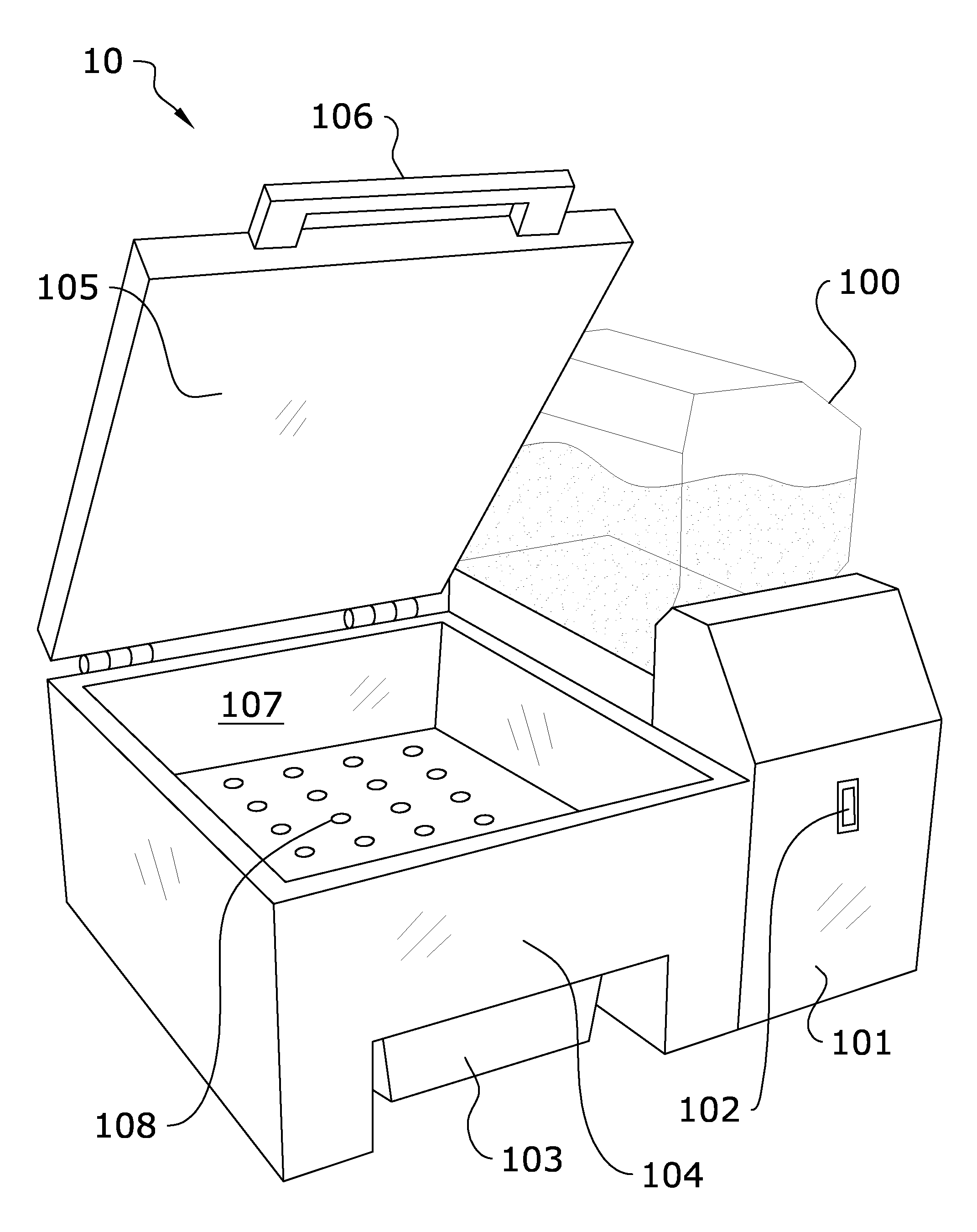
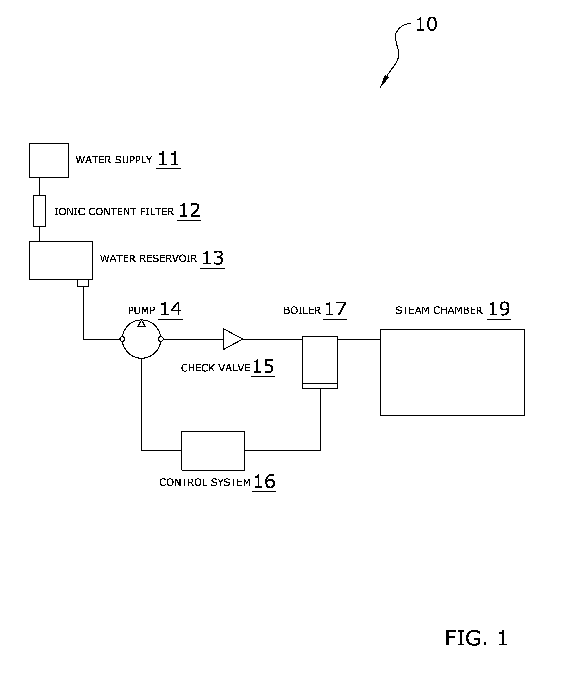
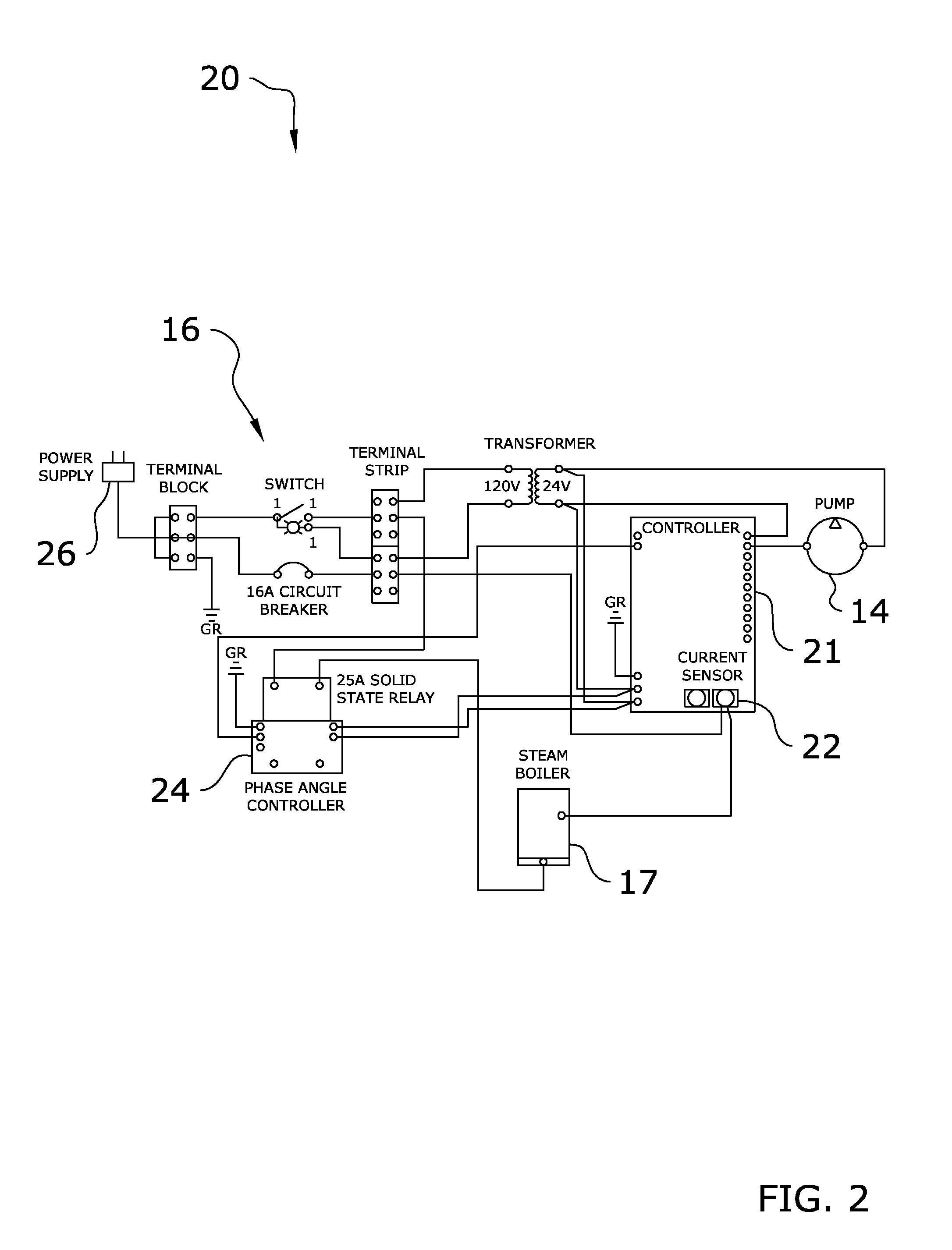
Turning now descriptively to the drawings, in which similar reference characters denote similar elements throughout the several views, FIGS. 1 through 9 illustrate a steam generator system 10 which comprises a supply of water 11 received by a heating tank 17 for producing steam in a continuous, intermittent, or a determinant amount, via electrodes and a control system 16. The steam is rapidly created via direct conversion of electrical energy to heat in the water molecules that are to become steam. Also possibly included are a water reservoir 13, filter 12, pump 14, check valve 15, and various optional embodiments for the heating tank 17.

FIG. 1 illustrates an exemplary flow diagram of the present invention illustrating a water reservoir 13 utilized for holding supply of water 11 to produce steam. It is appreciated that in an alternate embodiment, a water connection could be provided for a continuous supply in place of or in addition to the water reservoir 13. The water reservoir 13 ...


PUM


Abstract

A steam generator system for rapidly creating steam by a direct conversion of electrical energy to heat in ionic, water molecules. The system generally includes a supply of water having an ionic content to be received by a heating tank for contacting current-carrying electrodes to produce steam in a continuous, intermittent, or a determinant amount, via a control system. Also possibly included are a water reservoir, filter, pump, check valve, and various optional embodiments of the heating tank. The present invention also permits for controlling the supplied current input to the electrodes by the combination of ionic content added to the water, water level as controlled by the pump, and a phase angle controller and current sensor of an electrical circuit.

Description

STATEMENT REGARDING FEDERALLY SPONSORED RESEARCH OR DEVELOPMENTNot applicable to this application.BACKGROUND OF THE INVENTION1. Field of the InventionThe present invention relates generally to a steam generator and more specifically it relates to a steam generator system for rapidly creating steam by a direct conversion of electrical energy to heat in the water molecules and in current-controlled sequences to deliver a determinant amount of steam, intermittent amounts of steam or a continuous amount of steam.2. Description of the Related ArtAny discussion of the related art throughout the specification should in no way be considered as an admission that such related art is widely known or forms part of common general knowledge in the field.In steam use applications the need for rapid generation and replacement of steam is often required for speed of the work being performed by the steam. Different work to be performed by steam can require a determined amount of steam, intermittent a...

Claims


Application Information

Patent Timeline
IPC IPC(8): A21B1/22H05B3/60
CPCH05B3/60H05B2203/022H05B2203/021
Inventor COLBURN, MICHAEL G.BOGNER, STEPHEN J.
Owner WOOD STONE IDEAS
Learn More