Three-axes aerial dish pointing device with minimum radome encumbrance

a technology of pointing device and aerial dish, which is applied in the direction of antenna support/mounting, antenna adaptation in movable body, radiating element housing, etc., can solve the problems of reducing and affecting the installation of the whole aerial, reducing the radome encumbrance, and reducing the cost of the whole aerial installation

Inactive Publication Date: 2011-11-03
LOCATORI BRUNELLO
View PDF1 Cites 10 Cited by
  • Summary
  • Abstract
  • Description
  • Claims
  • Application Information

AI Technical Summary

Benefits of technology

[0042]In the case of a substantially plane dish, a further reduction is possible of the difference between radome diameter and dish diameter, such that a gap S as n

Problems solved by technology

A large radome often makes it difficult and expensive to install the whole aerial.
Moreover, stability problems may also occur due to strong wind exposure, as well as passengers and crew space reduction and movement hindrance arise.
Furthermore, poor received signals quality may result from a large radome at some dish orientations, since wave attenuation and aberration is likely to occur due to misalignment between wave direction and radome surface normal direction, as well as dish reception/transmission lobe distortion.
The rotation about skew axis is obtained by rotatably arranging an external gear of the elevation rotary structural section inside an internal gear of the cross elevation rotary structural section, an annular member whose thickness contributes to overall ae

Method used


Image

  • Three-axes aerial dish pointing device with minimum radome encumbrance
  • Three-axes aerial dish pointing device with minimum radome encumbrance
  • Three-axes aerial dish pointing device with minimum radome encumbrance

Examples


Embodiment Construction

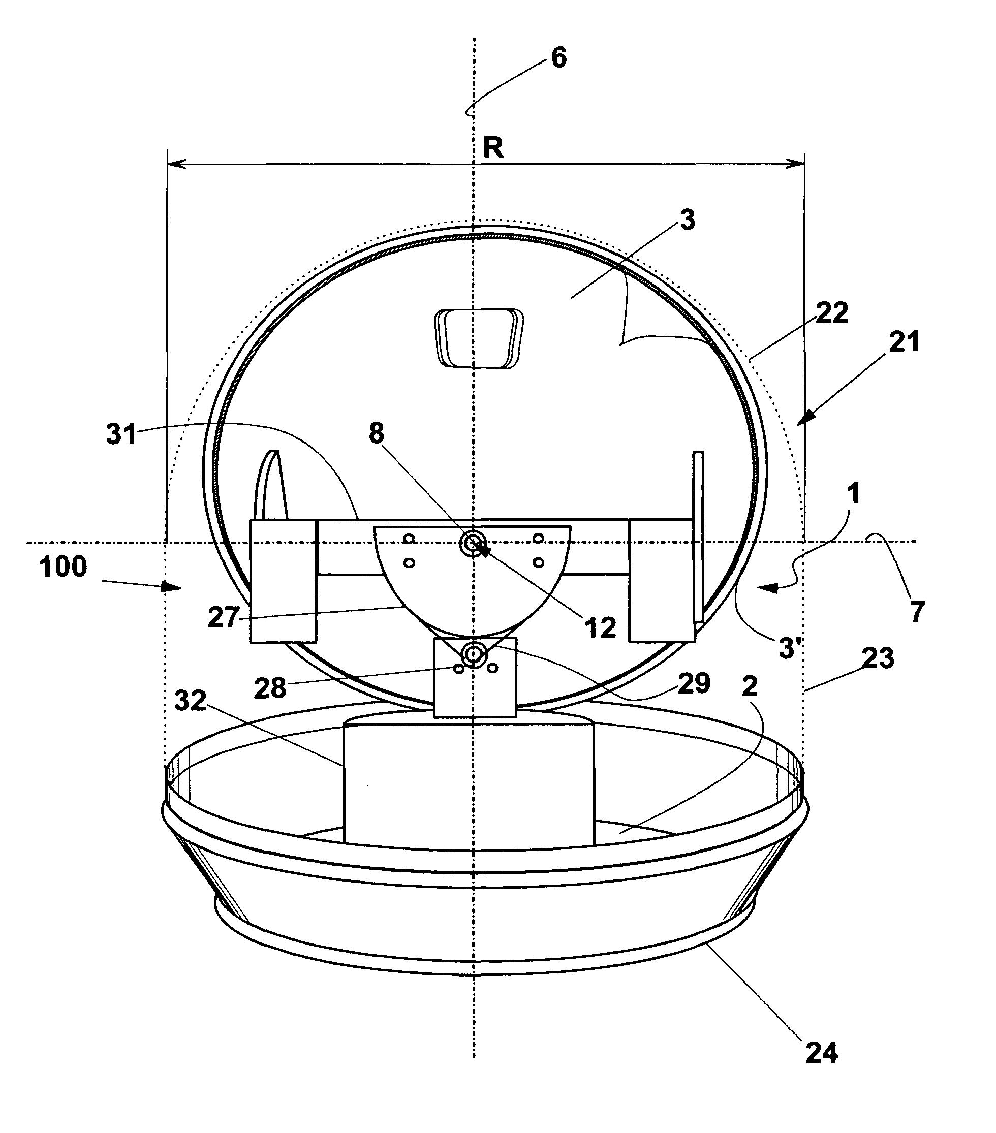
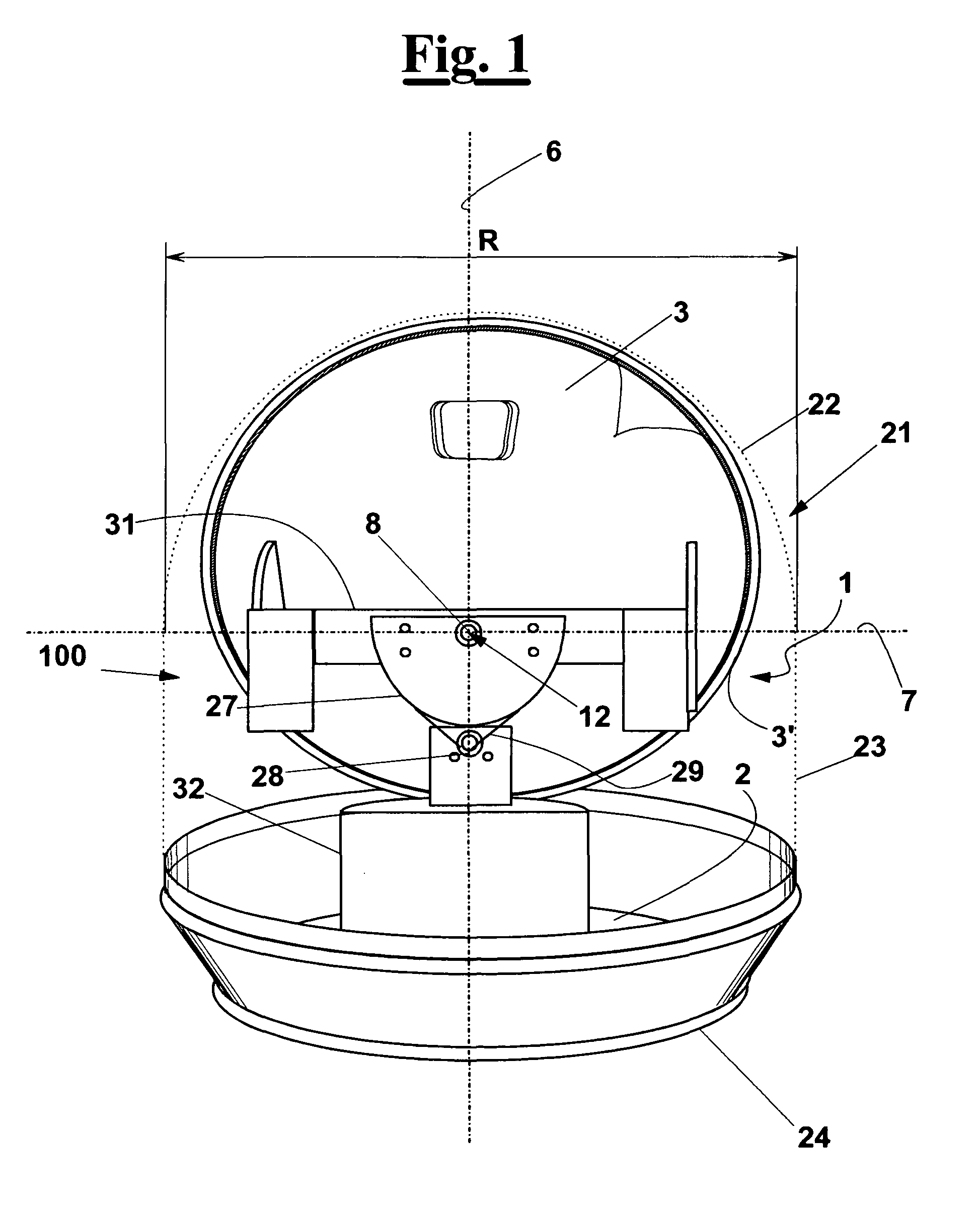
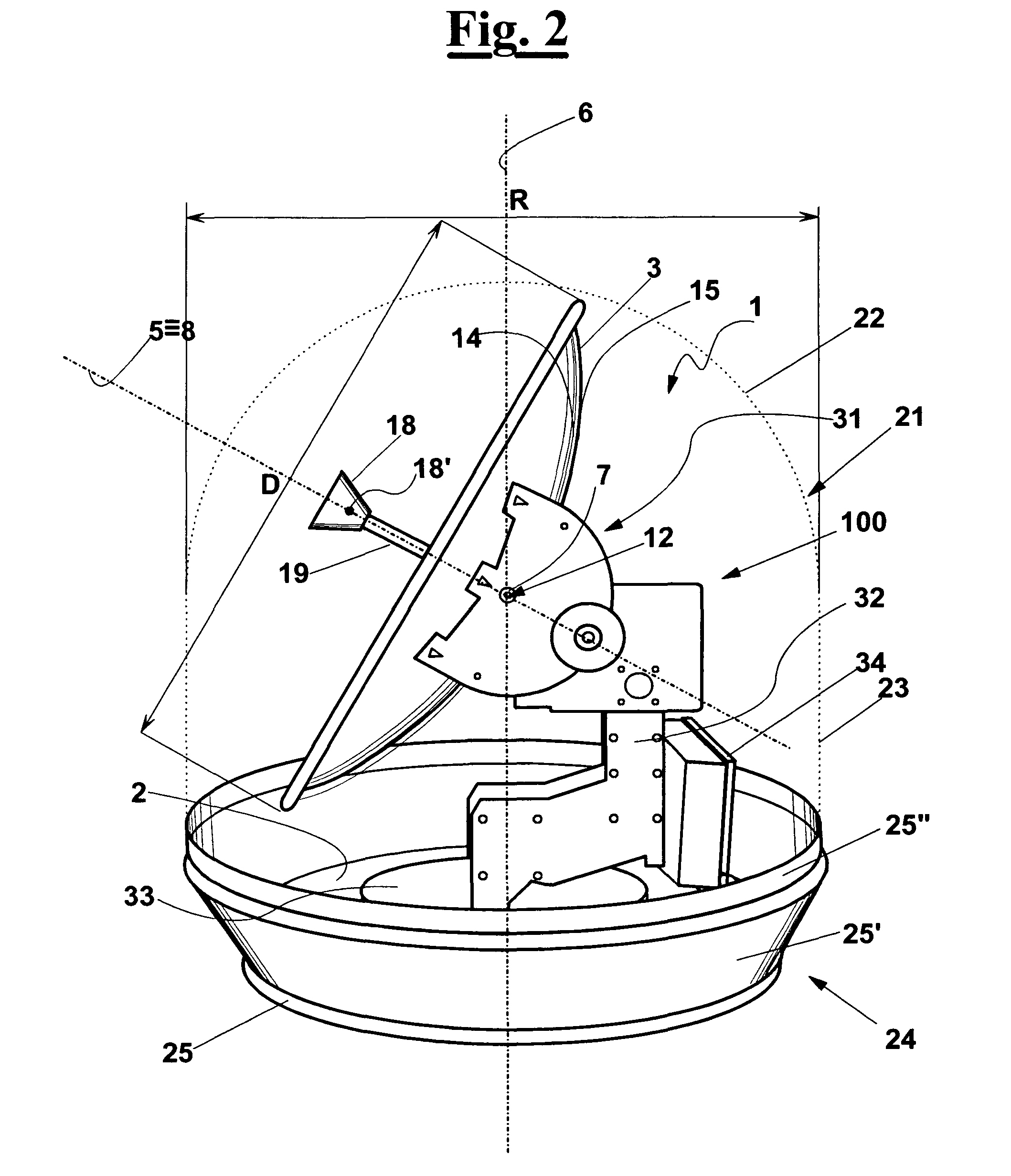
[0056]With reference to FIGS. 1, 2 and 4, a dish antenna 1 is shown that comprises:[0057]a dish 3 which has a rear side 15, a front side 14 in use directed towards a remote receiver / sender 10 according to a pointing axis 5 (FIG. 4);[0058]a support 2;[0059]a pointing device 100 which is provided with a dish position adjusting means suitable for carrying out respective rotations about three axes. The position of dish antenna 1 with respect to remote sender / receiver 10, apart from the mutual distance can be defined by azimuth angle δ′ and elevation angle 7′. Accordingly, rotations of dish 3 are provided about:[0060]an azimuth axis 6 integral to support 2, to adjust an azimuth angle δ′ formed between pointing axis 5 and a prefixed reference cardinal direction 9′ (FIG. 4);[0061]an elevation axis 7 integral to dish 3, to adjust an elevation angle 7′ formed between pointing axis 5 and a predetermined line 5′ that lies on the plane 11 defined by pointing axis 5 and by azimuth axis 6 (FIG. 4...


PUM


Abstract

A pointing device for real-time pointing the dish of a dish antenna (1), in particular a marine dish antenna, to be housed within a radome (21). The antenna comprises a dish (3) and a dish position adjusting means that achieves adjusting motions about an azimuth axis (6), an elevation axis (7) and a skew axis (8), the axes (6,7,8) having a minimum distance from a reference point (12), preferably the centre point (13) of a domed portion (22) of radome (21), wherein the reference point (12) is located closer to the front side (14) of the dish than to the rear side (15) of it, and wherein the dish position adjusting means comprises a driving actuating portion (27) integral to the support (2) and a driven actuating portion (28) integral to the dish (3) are provided which cooperate with each other to actuate the rotation about the skew axis (8), the driven actuating portion (28) extending within the profile of the dish (3). This way, the adjusting motions are carried out defining a substantially spherical space portion (26), whereby it is possible to house the dish antenna (1), in particular a Cassegrain type dish antenna, in radome whose diameter is smaller with respect to radome-housed dish antennas that are equipped with prior art pointing devices.

Description

FIELD OF THE INVENTION[0001]The present invention relates to a device for moving an aerial dish according to three rotational axes, in particular a marine satellite aerial dish.STATE OF THE ARTTechnical problem[0002]Dish antennas are normally equipped with a manual or preferably an automatic device for pointing the dish towards a desired satellite. If the dish has to be installed on a vehicle, in particular a watercraft, a pointing device must be provided which is suitable for carrying out a substantially real-time movement of the dish, corresponding to each movement of the vehicle, to keep on the communication.[0003]A dish orientation can be defined by three angles:[0004]the azimuth angle, which is formed between a pointing axis of the dish and a prefixed reference cardinal direction, an azimuth angle change being defined by a rotation about an azimuth axis;[0005]the elevation angle, which is formed between the pointing axis and a predetermined line that lies on a plane defined by ...

Claims


Application Information

Patent Timeline
IPC IPC(8): H01Q1/42
CPCH01Q1/18H01Q1/34H01Q19/13H01Q3/08H01Q1/42
Inventor LOCATORI, BRUNELLO
Owner LOCATORI BRUNELLO
Why Eureka
Try Eureka