Overvoltage protector

a technology of overvoltage protector and resistor, which is applied in the direction of emergency protective arrangement details, electrical equipment, and arrangements responsive to excess voltage, can solve the problems of unfavorable operation test, unwarranted increase of varistor leakage current at operating voltage, and defect of overvoltage protector signaling, etc., to achieve easy measurement and evaluation, display and prevent the effect of resistor damag

Inactive Publication Date: 2011-11-03
PHOENIX CONTACT GMBH & CO KG
View PDF6 Cites 10 Cited by
  • Summary
  • Abstract
  • Description
  • Claims
  • Application Information

AI Technical Summary

Benefits of technology

[0020]According to one preferred configuration of the third version in which the overvoltage protector has both a gas-filled surge arrester or a spark gap and also a suppressor diode as overvoltage limiters and in which there is a decoupling resistor between the gas-filled surge arrester or the spark gap and the suppressor diode, the optical coupler is connected parallel to the decoupling resistor. An overvoltage protector with a gas-filled surge arrester, a suppressor diode and a decoupling resistor is known from the prior art, especially in the MSR domain. To monitor the state of the suppressor diode, the optical coupler, as a monitoring component, is simply connected in parallel to the decoupling resistor which is present anyway. For high-resistance termination of the overvoltage protector, the current through the decoupling resistor corresponds to the current through the suppressor diode so that, by detecting the current through the decoupling resistor using the optical c

Problems solved by technology

Due to ageing, prior damage by discharge processes and intermittently occurring overvoltages (TOV) in the range of seconds, an unwanted increase of the leakage current of the varistor at operating voltages occurs, especially in overvoltage protectors with a varistor as the overvoltage limiter.
However only one defect of the overvoltage protector can be signaled by such an integrated display.
Since overvoltage prot

Method used


Image

  • Overvoltage protector
  • Overvoltage protector
  • Overvoltage protector

Examples


Embodiment Construction

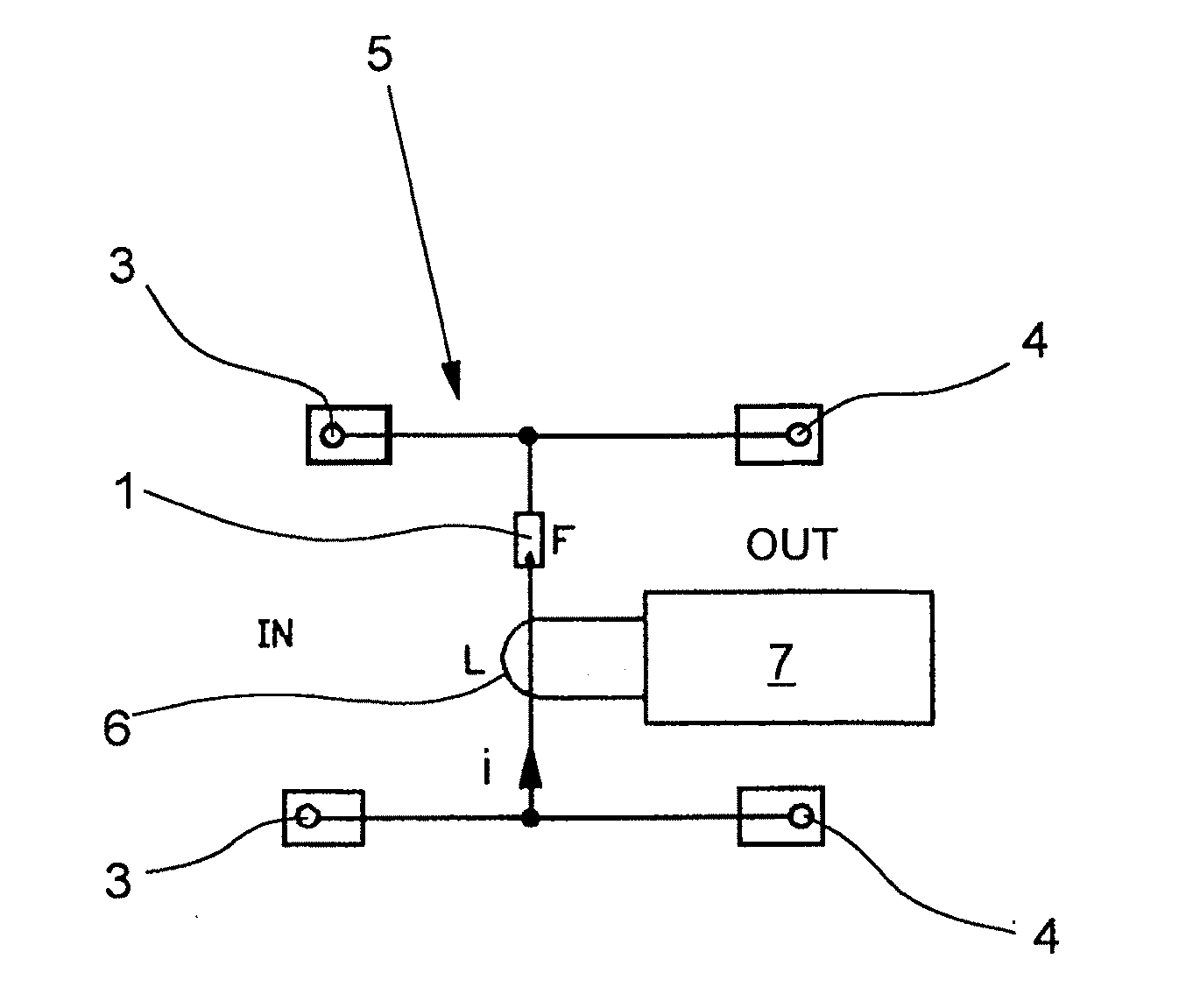
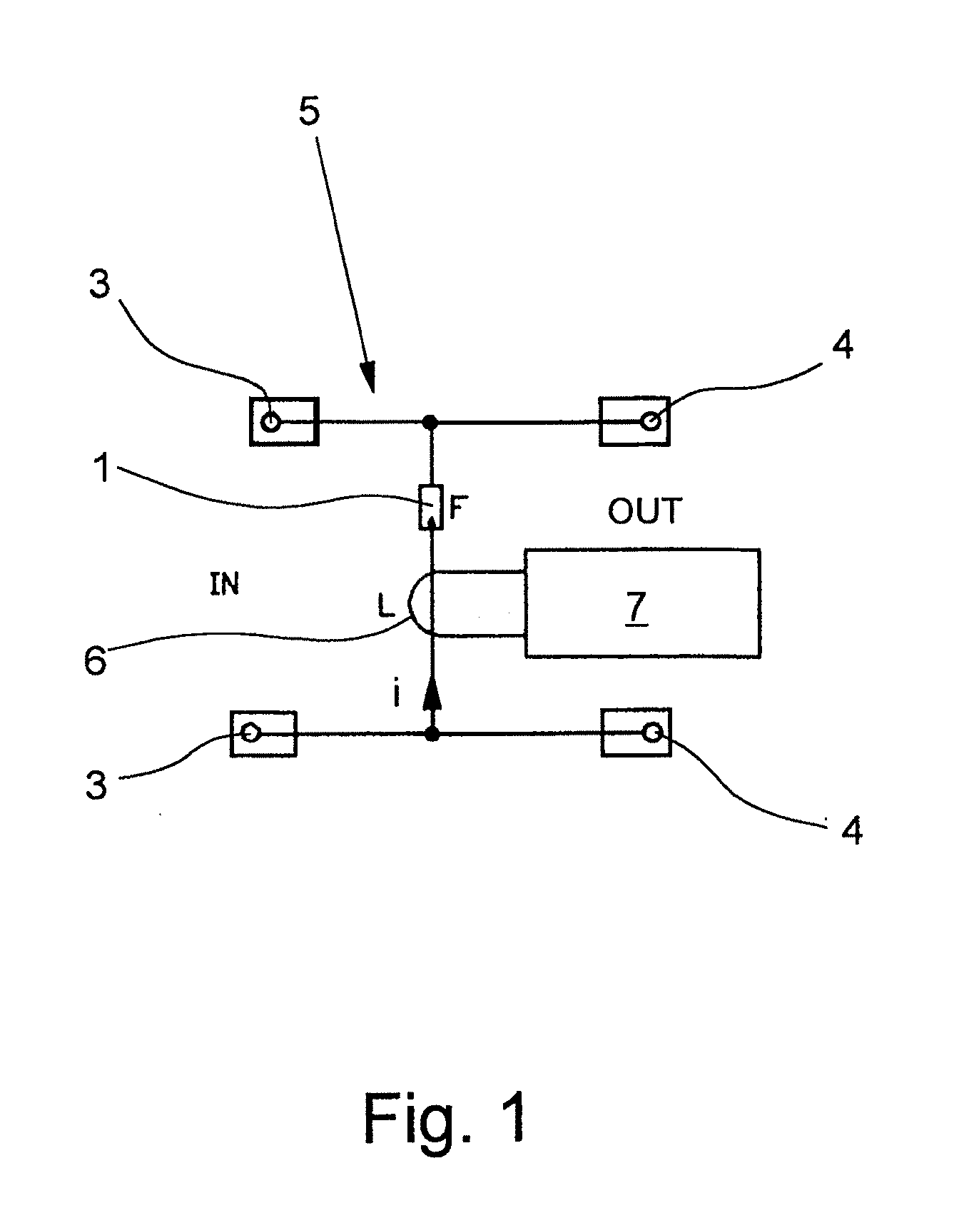
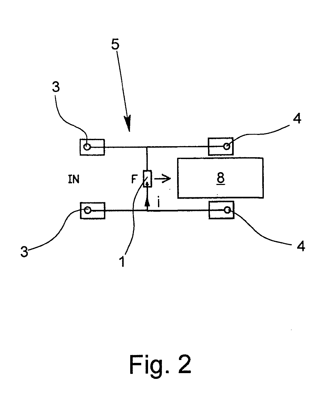
[0032]The figures each show a simplified circuit diagram of a respective version of the overvoltage protector in accordance with the invention. In the circuit diagrams, only the overvoltage limiter or limiters and a monitoring component are shown. FIGS. 1 to 3 each show an exemplary embodiment in which the overvoltage limiter is a gas-filled surge arrester 1. In the exemplary embodiments according to FIGS. 4 and 5, in addition to a gas-filled surge arrester 1 for coarse protection, there is also a suppressor diode 2 for precision protection. The simplified circuits shown in the figures have two input terminals 3 for connection of two lines and two output terminals 4 for connection of the device to be protected, for example, a sensor or a control. There can be other terminals, especially a ground terminal, even if they are not shown in the figures.

[0033]It is common to the exemplary embodiments according to FIGS. 1 to 4 that a monitoring component is assigned to the gas-filled surge ...


PUM


Abstract

An overvoltage protector having a housing and at least one overvoltage limiter arranged in the housing, especially a gas-filled surge arrester (1), a suppressor diode (2) or a varistor. The functional ability and the state of the overvoltage protector can be controlled during operation by associating a monitoring component with the overvoltage limiter which detects a current (i) flowing over the overvoltage limiter component, and by providing an evaluation unit that evaluates the signal of the monitoring component.

Description

BACKGROUND OF THE INVENTION[0001]1. Field of the Invention[0002]The invention relates to an overvoltage protector with a housing and with at least one overvoltage limiter which is located in the housing, the overvoltage limiter being especially a gas-filled surge arrester, a spark gap, a suppressor diode or a varistor.[0003]2. Description of Related Art[0004]Overvoltage protection can be divided into different areas of application. Here, it is distinguished between overvoltage protection for power supply, for measurement, open-loop and closed loop control (MSR) technology and for information technology and telecommunications. Interfaces of MSR technology are far more sensitive to overvoltages than power supply systems. For overvoltage protection, therefore, in the MSR domain, generally, overvoltage protectors with combined protective circuits are used, at least one overvoltage limiter being used for coarse protection and at least one overvoltage limiter being used for precision prot...

Claims


Application Information

Patent Timeline
IPC IPC(8): H02H9/04
CPCH02H3/044H02H9/04H02H1/0069H02H9/042
Inventor BRAND, FRIEDRICH-ECKHARDPFOERTNER, STEFFEN
Owner PHOENIX CONTACT GMBH & CO KG
Why Eureka
Try Eureka