Method for distributed mobile communications, corresponding system and computer program product

a mobile communication and distributed technology, applied in the field of mobile communication technology, can solve the problems of limited scalability and lack of flexibility in architecture, and achieve the effect of efficient application of these algorithms

Active Publication Date: 2011-11-03
TELECOM ITALIA SPA
View PDF11 Cites 158 Cited by
  • Summary
  • Abstract
  • Description
  • Claims
  • Application Information

AI Technical Summary

Benefits of technology

[0027]In an embodiment, the arrangement as described herein is an architecture of a distributed antenna system (DAS), which provides a high level of flexibility and scalability.
[0029]Embodiments of the DAS architecture disclosed herein may also provide throughput reduction of the signals transmitted on the fiber with respect to the prior-art DAS architecture shown in FIGS. 1 and 2. A throughput reduction may be particularly important considering that broadband wireless communication systems, like for example LTE and WiMAX, are capable of providing aggregate throughput per cell in the order of hundred of Mbits per second. The more efficient utilization of the transmission resources between the central unit CU and the remote units RU may thus permit to increase the maximum number of remote units that may be connected e.g. to a given fiber ring. Such a throughput reduction may also permit to use central units and remote units belonging to different communication standards on the same fiber. For example, it may be possible to operate with a single fiber ring remote units, which support both a CDMA based communication system and an OFDM based communication system.

Problems solved by technology

This architecture lacks flexibility, because any change in the algorithms used may involve a software and / or hardware modification in the central unit CU.
Besides, the scalability in terms of maximum number of remote units connected to a given central unit may be limited.

Method used


Image

  • Method for distributed mobile communications, corresponding system and computer program product
  • Method for distributed mobile communications, corresponding system and computer program product
  • Method for distributed mobile communications, corresponding system and computer program product

Examples


first embodiment

[0072]In a first embodiment, the signal transmitted on the fiber is the signal at the output of the resource mapping block 136 where the users are still separated in the frequency domain.

[0073]This first architecture is shown in FIG. 5 for the transmitter portion of an OFDM based DAS system, which receives data e.g. via a conventional S1 interface. Specifically, the baseband functionalities are split between a central unit CUOFDM and remote units RUOFDM.

[0074]In this embodiment, the central unit CUOFDM still performs the operation of the resource mapping block 136, and all prior operations, such as channel coding, H-ARQ, interleaving, modulation and MIMO processing, at a block 12a (i.e. the operations of blocks 126 to 134 in FIG. 3).

[0075]In the exemplary embodiment illustrated, the NS resource grids RG at the output of the resource mapping block 136 are transmitted e.g. column by column over the fiber link 16. As mentioned in the foregoing, the data at the output of the resource ma...

second embodiment

[0112]A second embodiment takes the foregoing into account by providing the same level of flexibility in terms of user based processing at the remote units RU, but at the same time retaining compatibility with the OBSAI and CPRI standards. Compatibility with the OBSAI / CPRI standards is counterbalanced by the fact that the throughput over the fiber links remains substantially the same as in the prior-art DAS architecture shown in FIGS. 1 and 2.

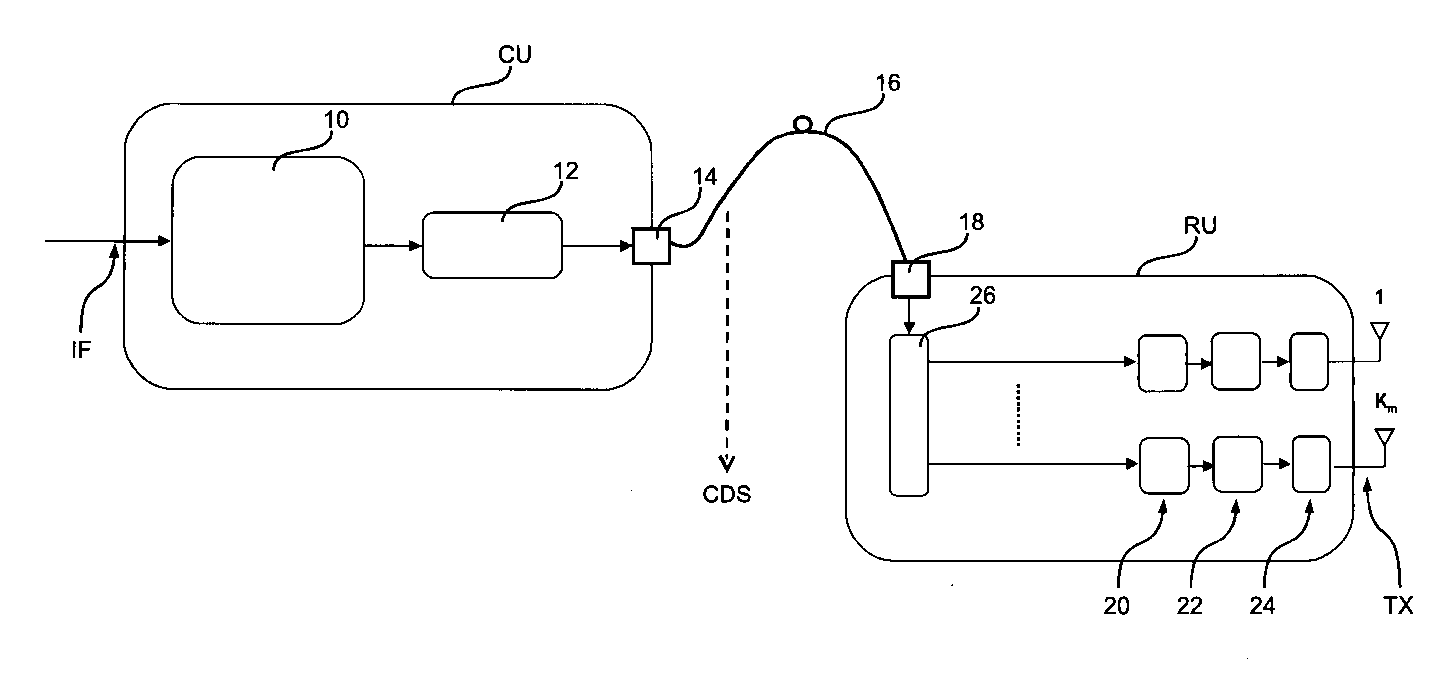
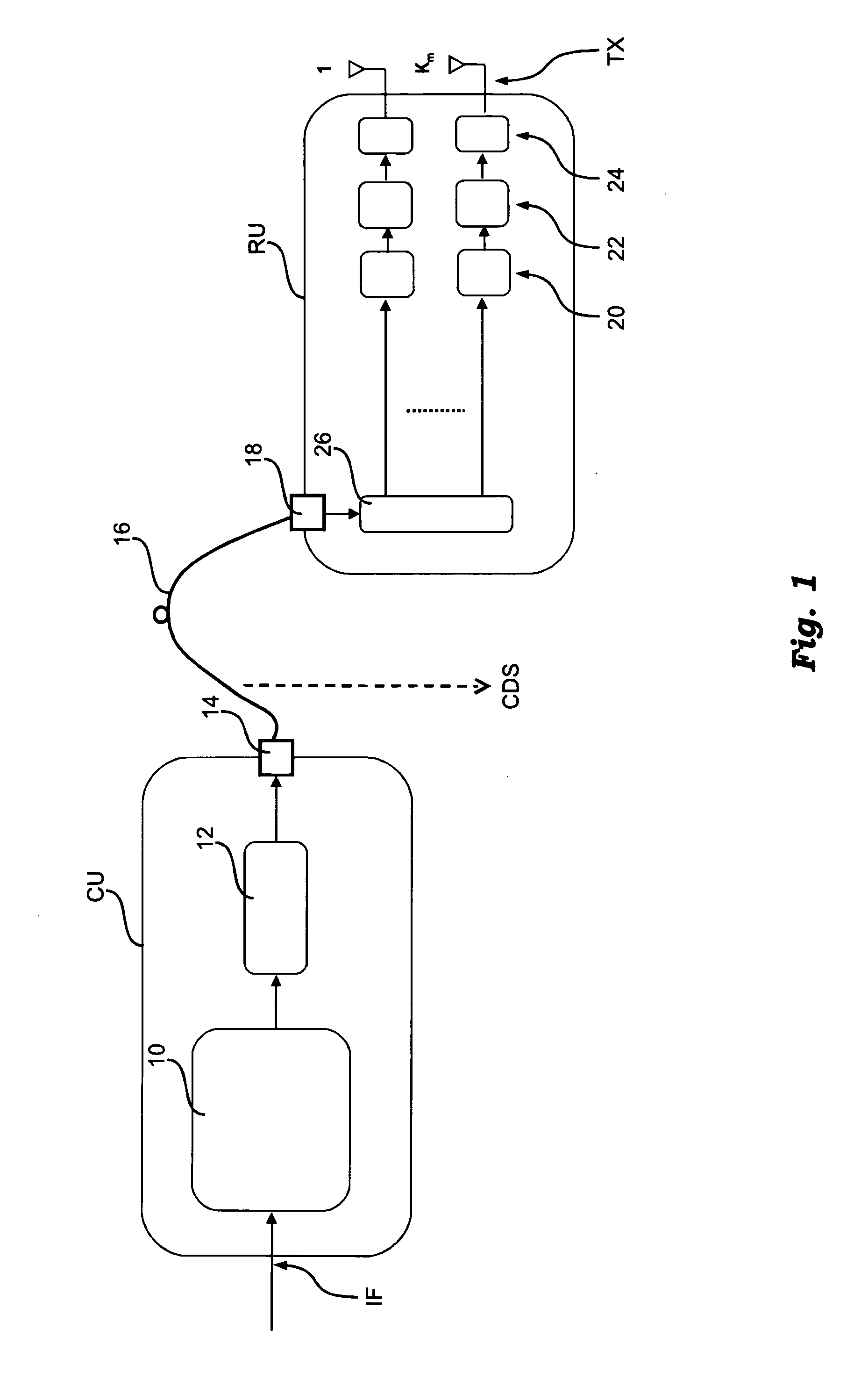
[0113]This embodiment is shown in FIG. 7 for the downlink transmission part. Substantially, this embodiment is based on the DAS architecture shown with respect to FIG. 1.

[0114]A central unit CUOFDM includes a block 10, which implements the higher layer protocols (L2 / L3), and a block 12, which performs the physical layer (L1) signal processing operations up to the generation of the composite digital baseband signal CDS. The composite digital baseband signal is then converted from electrical to optical at a block 14 and transmitted over the fiber...


PUM


Abstract

A method of arranging exchange of signals between user terminals in a cellular communication system and at least one base station. The base station includes a central unit and a plurality of remote units. The signals are exchanged between the central unit and the remote units as aggregated signals for plural user terminals. The signals are processed at the remote units as distinct signals each associated with a respective one of the plural user terminals.

Description

FIELD OF THE INVENTION[0001]This disclosure relates to techniques for providing radio access in mobile communication.[0002]More specifically, this disclosure has been developed with attention paid to its possible use in networks employing distributed antenna systems (DAS).DESCRIPTION OF THE RELATED ART[0003]A DAS system includes one or more Central Units (CU) connected preferably by means of a fiber link to a plurality of Remote Units (RU). The or each central unit is connected to the network of the telecommunication operator.[0004]FIG. 1 shows a conventional DAS architecture where a central unit CU receives data via an interface IF. The central unit CU performs the signal processing operations of a base station (BS) equipment. It includes a block 10 to implement the higher layer protocols (L2 / L3), such as Radio Resource Control (RRC), Radio Link Control (RLC) and Medium Access Control (MAC), and a block 12 to perform the physical layer (L1) signal processing operations up to the ge...

Claims


Application Information

Patent Timeline
Patent Type & Authority Applications(United States)
IPC IPC(8): H04W4/00
CPCH04B7/022H04W92/10H04W88/08H04W4/18H04B7/0617
Inventor BOLDI, MAUROGIANOLA, PAOLOMELIS, BRUNORUSCITTO, ALFREDO
Owner TELECOM ITALIA SPA
Why Eureka
Try Eureka