

Method of manufacturing polarizing member
- Summary
- Abstract
- Description
- Claims
- Application Information
AI Technical Summary
Benefits of technology
Problems solved by technology
Method used
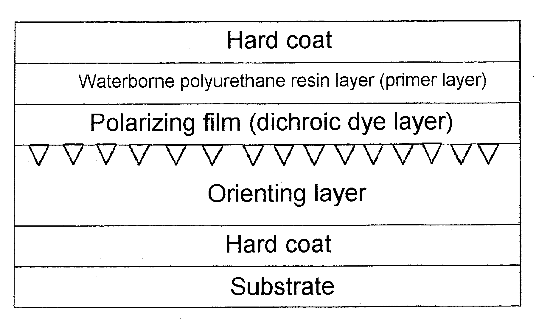
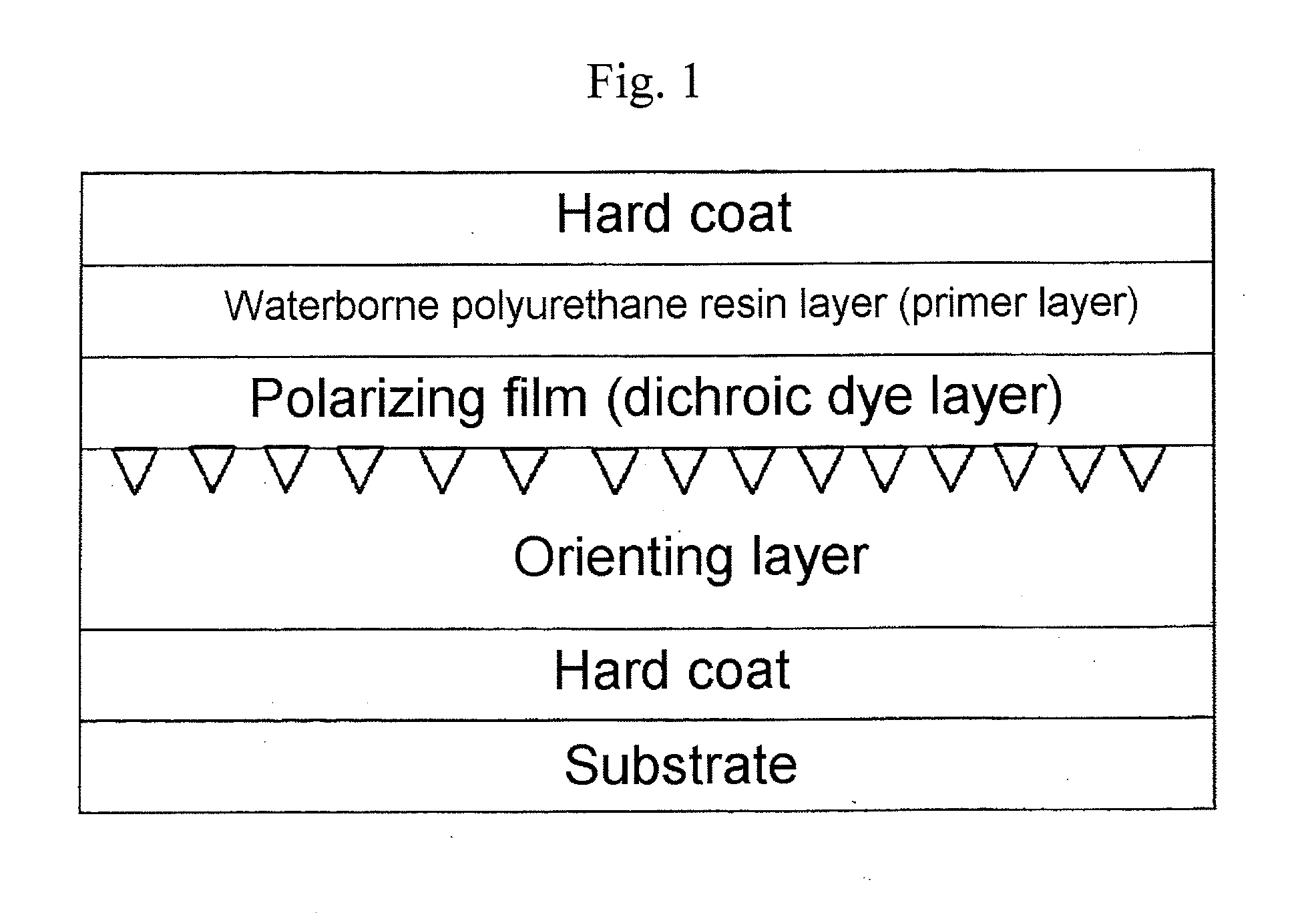
Image

Examples
example 1
Fabrication of a Polarizing Lens
[0119](1) Forming the Orienting Layer
[0120]A Phoenix lens (refractive index 1.53, with hardcoat, 70 mm in diameter, base curve 4, center thickness 1.5 mm, made by HOYA Corporation) was employed as the lens substrate. A SiO2 film was formed to a thickness of 0.2 μm by vacuum vapor deposition on the concave surface of the lens.
[0121]Abrasive-containing urethane foam (abrasive: Al2O3 particles with an average particle diameter of 0.8 μm, product name POLIPLA 203A, made by Fujimi Inc.; urethane foam: approximately the same shape as the curvature of the concave surface of the above lens) was employed to subject the SiO2 film that had been formed to uniaxial polishing under conditions of a rotational speed of 350 rpm at a polishing pressure of 50 g / cm2 for 30 seconds. The polished lens was rinsed in pure water and dried.
[0122](2) Forming the Polarizing Film
[0123]After drying the lens, 2 to 3 g of an aqueous solution of roughly 5 mass percent of water-solubl...
example 2
[0138]With the exception that a primer layer (waterborne resin layer) 0.44 μm in thickness was formed with a different quantity of waterborne polyurethane resin composition, polarizing lenses were obtained by the same method as in Example 1.
example 3
[0139]With the exception that the waterborne polyurethane resin composition was applied immediately, without allowing the lens that had been removed from the heating furnace to cool following the heat treatment, polarizing lenses were obtained by the same method as in Example 1.
PUM
| Property | Measurement | Unit |
|---|---|---|
| Thickness | aaaaa | aaaaa |
Abstract
Description
Claims
Application Information