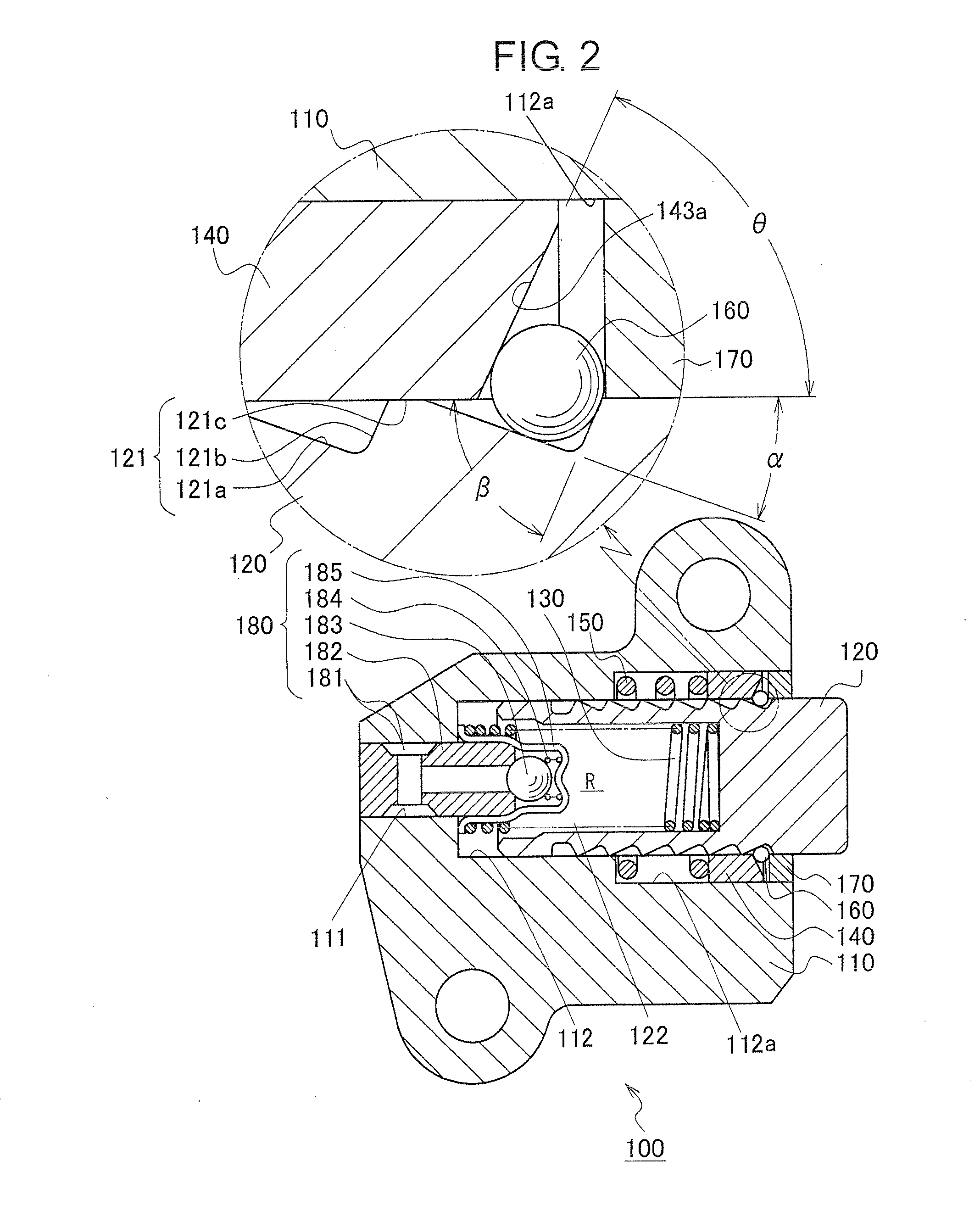
[0009]An aim of the invention is to solve the above-described problems by providing a ball-type tensioner that has one or more of the following effects. First, it reduces “flip-flop” noises by blocking retracting displacement of the plunger caused by forces applied to the plunger by a timing chain on starting an engine after the engine has been inoperative for a long time. Second, it eliminates the “beat note” generated by excessive chain tension caused by excessive protrusion of the plunger during operation of the engine, by permitting retracting displacement of the plunger. Third, it prevents seizure of the plunger. Finally the tensioner is simple, easy to assemble, and exhibits excellent durability.
[0011]The ball-type tensioner according to the invention is simple and easily manufactured and exhibits excellent durability. In addition, it can reduce “flip-flop” noises that occur on engine start-up by blocking retraction of the plunger when the engine is started after having been out of operation for a long time. Blocking of retraction of the plunger is achieved because the balls of the tensioner are sandwiched between the steep rear face of a rack tooth on the plunger and the inclined bottom surfaces of the ball-guiding grooves in the annular ball seat, while still in contact with the gradually sloping forward face of a rack tooth on the plunger.
[0012]When the chain tension drops as the timing chain becomes loose and the plunger protrudes, the balls, which are in contact with the gradually sloping forward face of a rack tooth, are pushed radially outward, and cause the annular ball seat to move in the retracting direction. At this time the balls are no longer sandwiched between the steep rear face of a rack tooth on the plunger and the inclined bottom surfaces of the ball-guiding grooves. The balls can then
cross over a tooth of the rack permitting the plunger to advance. After crossing a tooth, the balls are pushed radially inward by the inclined surfaces of the ball-guiding groove and toward a gradually sloping forward face of another rack tooth, whereupon the balls are again sandwiched between the steep rear face of another rack tooth on the plunger and the inclined bottom surfaces of the ball-guiding grooves, and the plunger is latched in a more advanced position. The advancing displacement of the plunger thus balances the chain tension in a repeating series of operations, ensuring optimal tension in the timing chain.
[0013]If excessive chain tension occurs when the plunger is an excessively protruding condition, the force exerted through the balls by the steeply sloped rearward side of a rack tooth pushes the annular ball seat rearward, away from the sealing plate in the retracting direction. The balls move outward and
cross over one rack tooth, whereupon the balls are pushed inward and against a gradually sloping forward face of a next rack tooth and again sandwiched again between a steep rearward face of a rank tooth and the inclined bottom surfaces of the annular ball seat. By a series of repetitions of this operation, the plunger can be made to retract.
Seizing of the plunger can thereby be prevented and the “beat note” or “whirring”
noise that is generated by increased chain tension when the plunger is in an excessively protruding condition can be eliminated.
[0014]In a preferred embodiment, the slopes of the forward and rearward surfaces of the rack teeth are sufficiently steep that the center of a ball disposed between a rearward surface and an adjacent forward surface of rack tooth is always within the annular groove. Because the centers of the balls always reside within the annular groove in the wall of the plunger-accommodating hole, the balls always roll between a steeply sloping rear face of an annular rack tooth on the plunger and the inclined bottom surfaces of the annular ball seat without falling out of the annular groove. Accordingly, it is possible to achieve quick and steady response to increases and decreases in chain tension.
[0015]The annular ball seat preferably has at least three ball-guiding grooves formed therein, and the ball-guiding grooves in the annular ball seat are disposed at uniform intervals around the ball seat. The use of at least three uniformly spaced bell-guiding grooves makes it possible to eliminate eccentric radial loads as the plunger advances and retracts. Accordingly, the forces acting on the annular ball seat are equally dispersed, the plunger can advance and retract smoothly in response to changes in chain tension, and the useful life of the annular ball seat can be extended.

