
Method and plant for the production of flat rolled products

a technology of flat rolled products and production methods, applied in metal working apparatuses, manufacturing tools, work heating devices, etc., can solve the problems of loss in production, inability to insert a second casting line in endless process, and inability to have an intermediate buffer between, etc., to achieve the effect of shortening the tunnel

Active Publication Date: 2011-11-10
DANIELI & C OFF MEC SPA
View PDF1 Cites 17 Cited by
  • Summary
  • Abstract
  • Description
  • Claims
  • Application Information

AI Technical Summary

Benefits of technology

[0034]to have a buffer between the casting machine and the rolling mill that allows to absorb the down times of the rolling mill due to incidents or roll changes, without needing to stop the casting and therefore without losing production and without penalizing the steel works upstream;
[0110]In another possible variant, the first or the last part of the tunnel furnace is replaced by an inductor, so as to shorten the tunnel.

Problems solved by technology

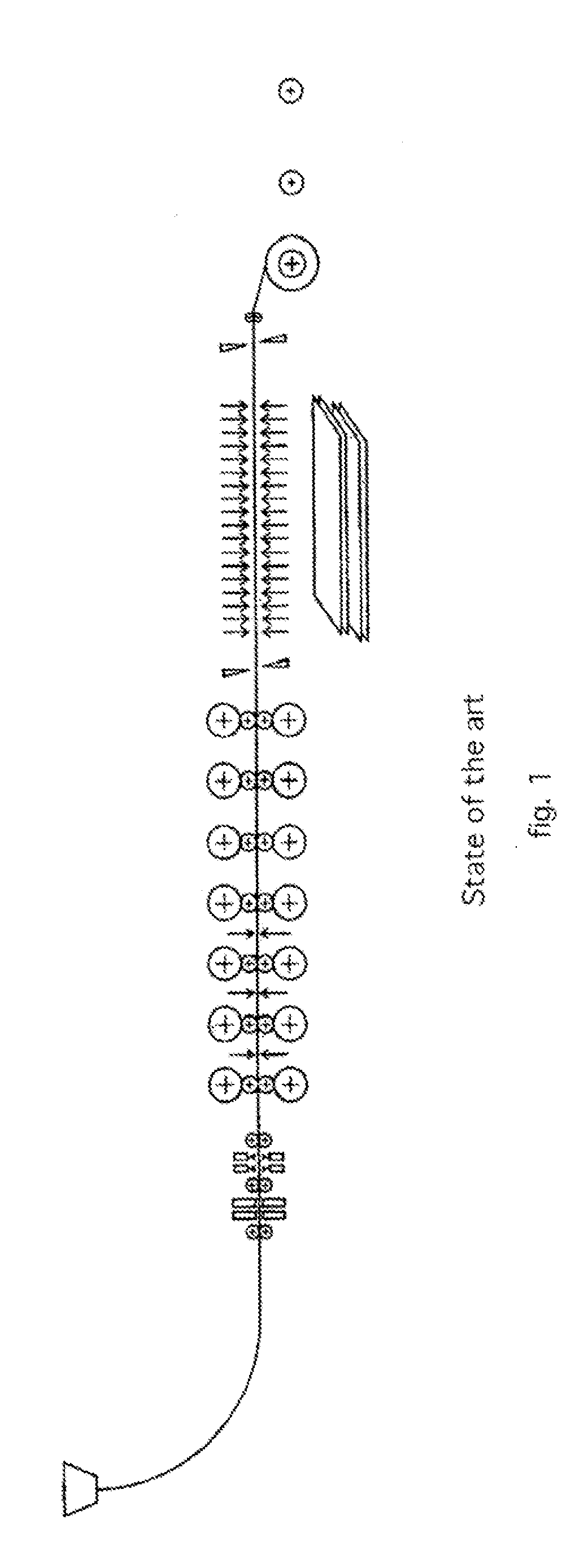
Unfortunately the endless process, like the one shown for example in the patent EP 1868748, the layout plan of which is shown in FIG. 1, is very rigid for the reasons given below.
Moreover, as the rolling train is located immediately at the exit of the continuous casting machine in the endless process, there is no possibility of having an intermediate buffer between the two rolling and casting processes which are rigidly connected.
Therefore each minimum stoppage of the rolling mill and / or the strip winding machines, for example due to a programmed change of the rolling rolls, in order to carry out controls, due to accidents, sudden interruptions or minor breakdowns, requires that the continuous casting process and also that of the steel works upstream is stopped, with a loss in production.
Moreover, the endless process does not allow to insert a second casting line so as to increase the productivity of the plant.
Finally, the endless process has very little flexibility in the production changes (slab width and thickness).
The existing solutions have pros and cons but do not however manage to satisfy to a great extent the needs of a plant which is both flexible and versatile so as to serve the market competitively.
In particular the processes currently existing have the following characteristics which are also summarized in the comparison table shown in FIG. 5:Endless: optimal for producing ultra-thin thicknesses from 0.7 to 0.9 mm in that it eliminates the entry of the head of the bar in the stands, therefore with lower wear on the rolls and with fewer risks of blockages, it allows a stationary rolling, but on the other hand it cannot produce some types of steel, it has a low use factor of the plant, a low yield and it does not have the possibility of inserting a second line to increase production;Coil-to-coil: allows to produce the whole range of castable steels with a thin slab caster, it has high use factor of the plant and high yield.
On the other hand, it has a low productivity in the production of ultra-thin strip (0.7-0.9 mm) in that the process necessarily entails that the first and the last coil of the slab are produced with increased thickness; it reduces (by ¼ or ⅕), but does not eliminate the problem of the entrance of the bar into the stands of the rolling train, and finally, it increases the problems of entrance of the strip to the winding reels in that the speeds of advance of the strip are very high compared to the endless mode.

Method used


Image

  • Method and plant for the production of flat rolled products
  • Method and plant for the production of flat rolled products
  • Method and plant for the production of flat rolled products

Examples


Embodiment Construction

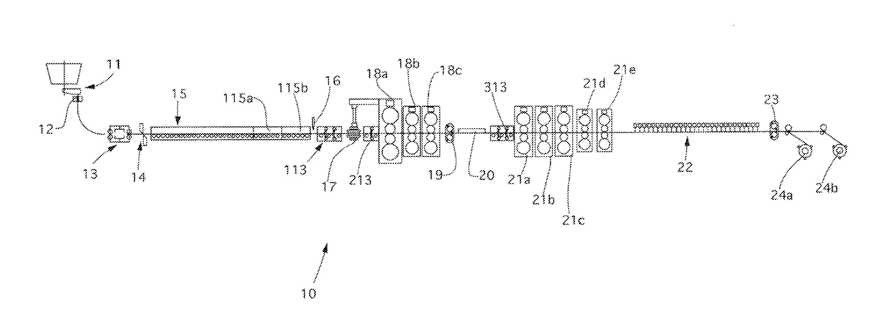
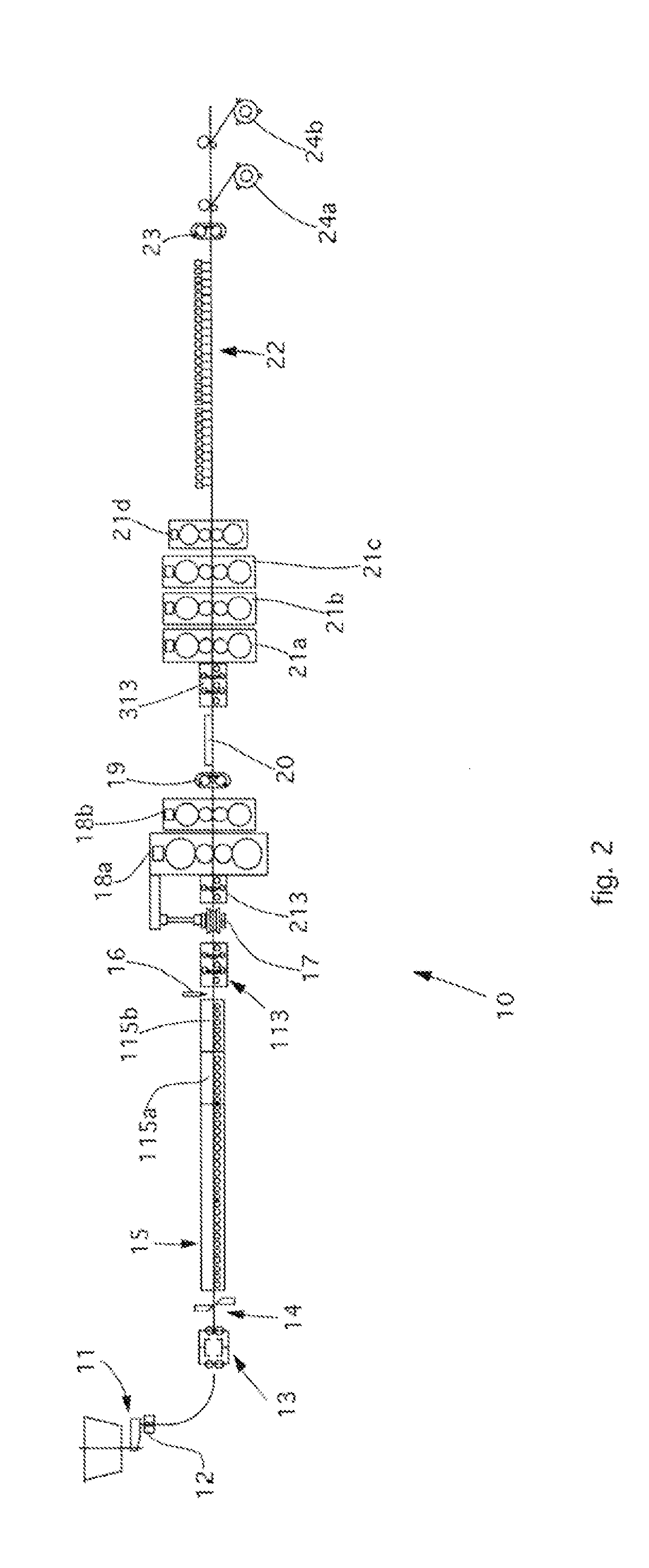
[0117]With reference to FIGS. 2-4, three possible lay-outs are shown of a casting / rolling line 10 for flat products that implements the principles of the present invention.

[0118]In particular, the lay-out in FIG. 2 is advantageously but not exclusively applied for ranges of thickness of the cast slab from 30 to 70 mm, and productivity from 600,000 to 2,000,000 ton / year.

[0119]The lay-out in FIG. 3 is advantageously but not exclusively applied for ranges of thickness of the cast slab from 60 to 100 mm, and productivity from 1,000,000 to 2,800,000 ton / year.

[0120]The lay-out in FIG. 4 is advantageously but not exclusively applied for ranges of thickness of the cast slab from 80 to 140 mm, and productivity from 1,500,000 to 3,500,000 ton / year.

[0121]In general, the line10 comprises as constituent elements:

[0122]a continuous casting machine 11 having an ingot mold 12;

[0123]a first descaling device using water 13;

[0124]a pendulum shears 14;

[0125]a tunnel furnace 15 having at least the penul...


PUM

PropertyMeasurementUnit
thicknessaaaaaaaaaa
thicknessaaaaaaaaaa
thicknessaaaaaaaaaa

Abstract

A rolling method in a rolling line, to obtain strip with a thickness varying from 0.7 mm to 20 mm, for steel which can be cast in the form of thin slabs with a thickness from 30 mm to 140 mm, the line includes a continuous casting device; a tunnel furnace for maintenance / equalization and possible heating; a rolling train having a roughing train and a finishing train; a rapid heating unit, with elements able to be selectively activated, interposed between the roughing train and the finishing train. For each lay-out of the rolling line, the position of the rapid heating unit which defines the number of stands which form the roughing train, disposed upstream of the unit, and the number of stands which form the finishing train, disposed downstream of the unit, is calculated as a function of the product of the thickness and speed of the thin slab.

Description

FIELD OF THE INVENTION[0001]The present invention concerns a method for the production of flat rolled products, such as strip or plate, and the relative production plant.BACKGROUND OF THE INVENTION[0002]Rolling plants disposed in a line with a continuous casting machine which produces thin slabs, or “thin slab casters”, are known.[0003]Such plants can be planned and configured for a substantially continuous rolling process, or “endless”, in which the cast product is rolled in a rolling train which is placed immediately at the exit of the continuous casting machine with which it is in direct contact.[0004]The fact that the rolling train is directly attached at the exit of the continuous casting machine in the endless process allows temperature not to be lost and, moreover, to exploit to the full the heat in the cast product and the low resistance to pressure in the first two-three rolling stands inasmuch as re-crystallization has not yet completely taken place, with consequent saving...

Claims


Application Information

Patent Timeline
Patent Type & Authority Applications(United States)
IPC IPC(8): B22D11/00B22D27/02B22D11/12
CPCB21B1/46B21B1/463B21B1/466Y10T29/49991B21B15/005B21B45/004B21B13/22B21B2201/08B21B2201/10
Inventor BENEDETTI, GIANPIETROBOBIG, PAOLO
Owner DANIELI & C OFF MEC SPA
Learn More