
Vehicle-mounted active vibration reducing device

a technology of active vibration reduction and vehicle, which is applied in the direction of vibration dampers, vibration suppression adjustments, shock absorbers, etc., can solve the problems of high installation cost, poor fuel economy, and heavy weight of dynamic dampers used on vehicles, so as to reduce the installation cost of dynamic dampers, reduce the installation space limitations, and reduce vibrations

Inactive Publication Date: 2011-11-10
HONDA MOTOR CO LTD
View PDF9 Cites 16 Cited by
  • Summary
  • Abstract
  • Description
  • Claims
  • Application Information

AI Technical Summary

Benefits of technology

Similarly, if piezo actuators are installed parallel to the dampers, then such piezo actuators require a large installation space. Further, such piezo actuators suffer large limitations on their installation space, incur a very high installation cost, and result in increased weight.
The present invention has been made in view of the above-noted drawbacks. It is an object of the present invention to provide a vehicle-mounted active vibration reducing apparatus, which reduces installation costs, reduces limitations on the installation space thereof, and achieves increased fuel economy by way of a reduction in weight.
Still another object of the present invention is to provide a vehicle-mounted active vibration reducing apparatus, which includes a single dynamic damper that is capable of reducing vibrations within a wide frequency range in at least one of a plurality of vibration reducing directions.
According to the present invention, therefore, the vehicle-mounted active vibration reducing apparatus, which includes a single dynamic damper, is capable of reducing vibrations in a plurality of directions. As a consequence, installation costs for the dynamic damper, as well as limitations imposed on the installation space, are reduced. Further, increased fuel economy is achieved by way of a reduction in weight.

Problems solved by technology

However, a dynamic damper for use on vehicles weighs several kilograms [kg] per unit.
If plural dynamic dampers are installed on a vehicle (target object), then a very high installation cost is incurred.
Further, the dampers suffer significant limitations on their installation space, and lead to poor fuel economy.
Similarly, if piezo actuators are installed parallel to the dampers, then such piezo actuators require a large installation space.
Further, such piezo actuators suffer large limitations on their installation space, incur a very high installation cost, and result in increased weight.

Method used


Image

  • Vehicle-mounted active vibration reducing device
  • Vehicle-mounted active vibration reducing device
  • Vehicle-mounted active vibration reducing device

Examples


first embodiment

A.

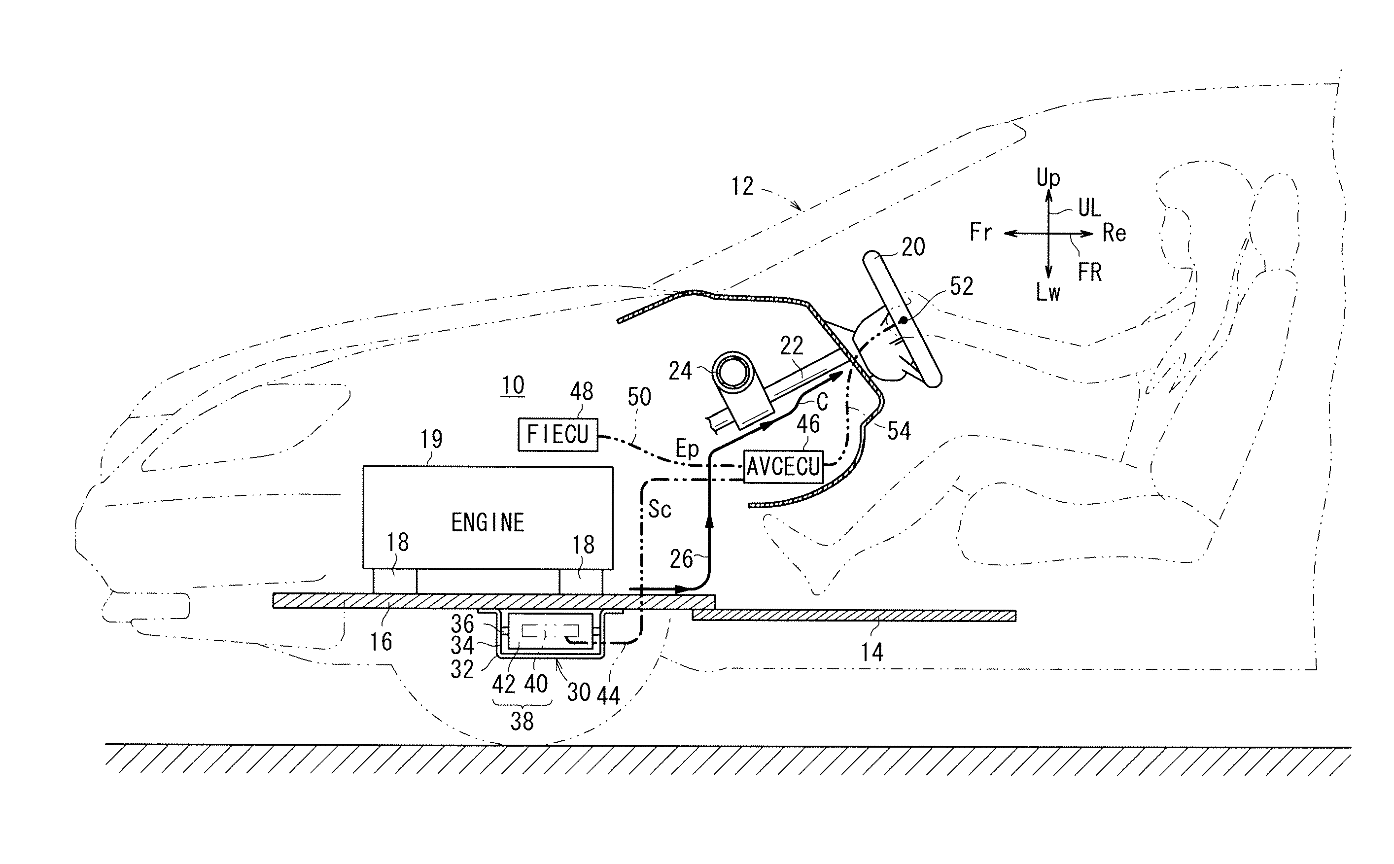
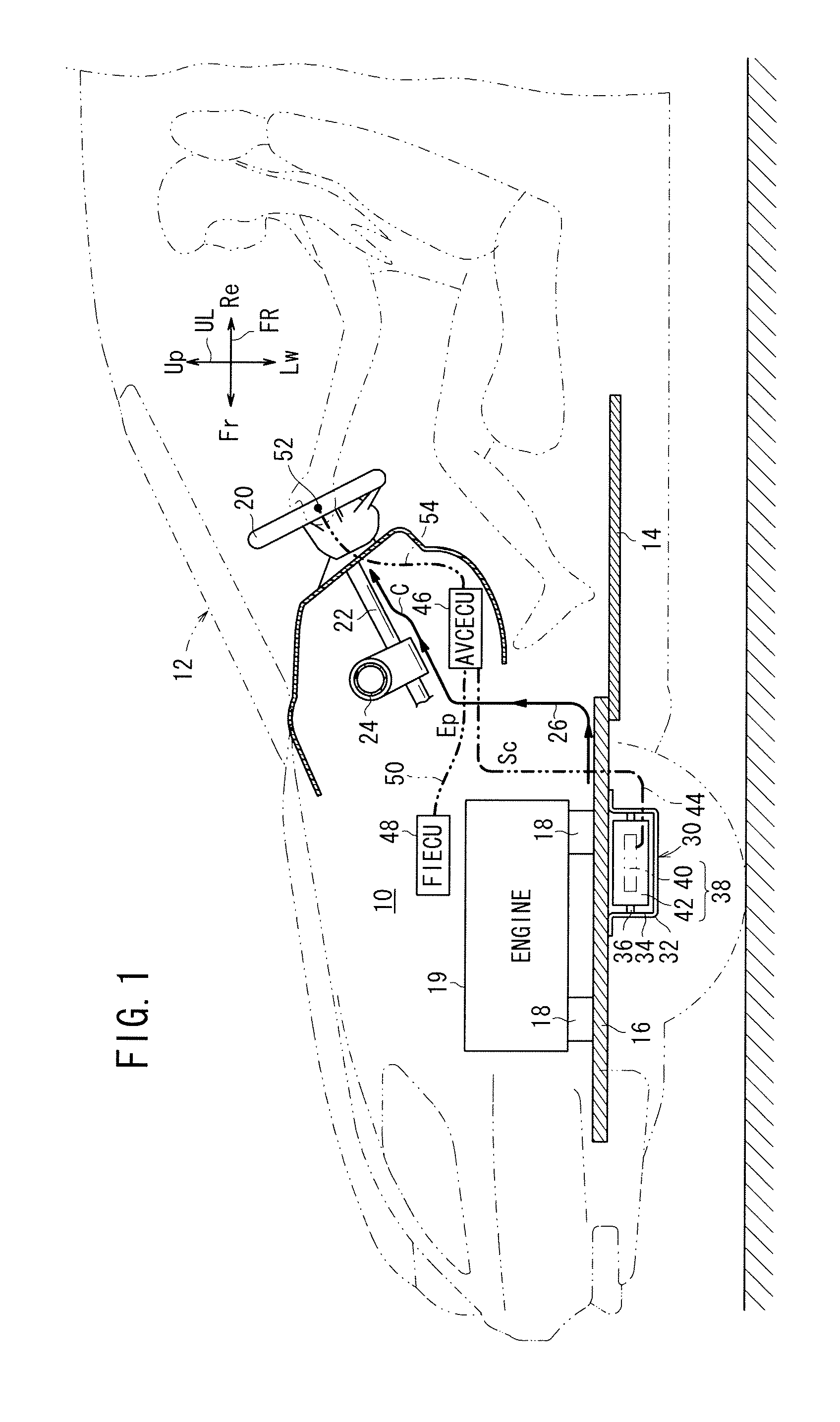
FIG. 1 schematically shows an arrangement of a vehicle 12 incorporating a vehicle-mounted active vibration reducing apparatus (hereinafter referred to as an “AVC apparatus (active vibration control apparatus)”) 10 according to a first embodiment of the present invention.

The vehicle 12 has a floor panel 14 and a subframe 16, which is mounted on a front portion of the floor panel 14 and serves as a vibration source proximity member, and a target object (first target object), which is controlled to attenuate vibrations thereof.

An engine 19 (internal combustion engine), which acts as a vibration source, is mounted on the subframe 16 through vibration attenuating rubber members 18.

A steering wheel 20, which serves as another target object (second target object) controlled to attenuate vibrations thereof, is supported on a steering shaft 22, which is rotatably supported by a steering hanger 24.

The steering hanger 24 is fixed, for example, to opposite front side panels, not shown. The fr...

second embodiment

B. Second Embodiment

FIGS. 8 and 9 show an AVC apparatus 10a according to a second embodiment of the present invention. In the AVC apparatus 10a, the bracket 32 of the dynamic damper 30 and the vibration sensor 52 are mounted on the subframe 16, such that the actuator 38 and the vibration sensor 52 are disposed in proximity to each other.

The AVC apparatus 10a, which is constructed as shown in FIGS. 8 and 9, has increased control stability, because the simulated transfer function Ĉ of a reference signal generator 64a of a control signal generator 70a is close to the value “1”, resulting in a minimum-phase system.

According to the second embodiment, the dynamic damper 30 is capable of attenuating vibrations in vertical directions UL of the subframe 16 at the resonant frequency f3, whereas the AVC apparatus 10a is capable of attenuating vibrations in forward and rearward directions FR at frequencies f1, f2 and f4.

The present invention may be applied to the subframe 16, as well as to atte...


PUM


Abstract

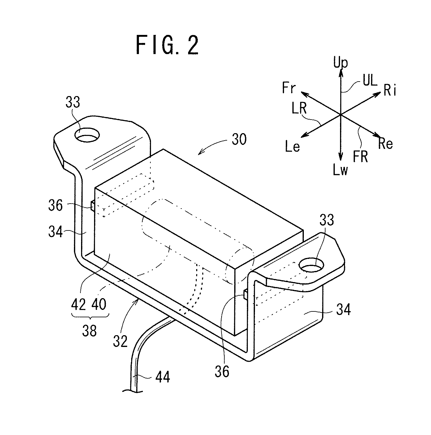
Provided is a vehicle-mounted active vibration reducing device wherein vibrations in a plurality of directions are reduced by a single dynamic damper. Since an actuator is attached so as to be supported by an elastic member attached to a bracket, the actuator can be used as a mass of a dynamic damper. The moving directions of the actuator are the forward and rearward directions, and are different from the moving directions of the dynamic damper using the actuator as a mass, i.e., the upward and downward directions. Accordingly, vibrations can be controlled in the forward and rearward directions which correspond to the moving directions of the actuator as well as the upward and downward directions which correspond to the moving directions of the dynamic damper.

Description

TECHNICAL FIELDThe present invention relates to a vehicle-mounted active vibration reducing apparatus (device) for reducing vibrations in a plurality of directions of a target object, which is controlled to attenuate vibrations.BACKGROUND ARTHeretofore, there have been employed dynamic dampers as vibration reducing apparatuses (vibration attenuators), as disclosed in Japanese Laid-Open Utility Model Publication No. 05-026745 and Japanese Laid-Open Patent Publication No. 2001-227582.Japanese Laid-Open Utility Model Publication No. 05-026745 reveals a vehicular auxiliary supporting apparatus, wherein an engine auxiliary such as an alternator or the like is disposed in a position aligned with a vibrational antinode of a subframe. In operation, the engine auxiliary oscillates in order to cancel out vibrations of the subframe, and hence the engine auxiliary acts as a dynamic damper.Japanese Laid-Open Patent Publication No. 2001-227582 discloses a dynamic damper including a mass mounted o...

Claims


Application Information

Patent Timeline
Patent Type & Authority Applications(United States)
IPC IPC(8): F16F15/02
CPCF16F7/1011F16F15/002F16F15/04F16F7/108
Inventor KOBAYASHI, YASUNORIINOUE, TOSHIO
Owner HONDA MOTOR CO LTD
Learn More