Structure

a technology for structures and structures, applied in the direction of containers, pliable tubular containers, large containers, etc., can solve the problems of inconvenient use, increased transportation costs, and inability to meet the needs of users, and achieve the effect of preventing damage to the bladder

Inactive Publication Date: 2011-11-10
PETERKEN NEIL TERRY
View PDF18 Cites 9 Cited by
  • Summary
  • Abstract
  • Description
  • Claims
  • Application Information

AI Technical Summary

Benefits of technology

[0115]Optionally, the present invention may include a bladder guard. Bladder guards may be positioned over portions of the bladder and the top frame segments to prevent damage to the bladder.
[0116]The clips of the roof spoke structure may fit overtop of the guard. Therefore, bladder guards prevent the clips and spoke structure from damaging the bladder.
[0117]Preferably, a series of tie downs may be used to secure the flexible cover to the tank thereby preventing unauthorised access into the tank.

Problems solved by technology

However, when a structure of large volume is required, this is often prohibitively costly as the volume of the structure significantly increases transport costs.
However, all suffer from inherent limitations including the intricate manner of their engineering, high relative cost, unsuitability for certain applications, or even failings to meet the purpose for which they are intended.
The method of connecting adjacent modules is fiddly and time consuming, with adjacent modules needing to be carefully aligned.
This takes time and skill.
These vertical stiffener means are required to be connected to the modules which again increases the construction time of the structure and involves considerable effort by users.
The combined effect of all the different component parts is that the structure is laborious to construct and install.
Further, they require considerable effort to manufacture each individual part thereby increasing production costs.
A tank such as this is not suitable for use as a large storage structure as it is unable to support its own weight and must be mounted in a bracket.
This limits its application to uses other than as a domestic water storage tank.
Further, it is unlikely that the tank will have sufficient strength to hold and store a large amount of material.
The storage tank disclosed by this patent is fiddly and time consuming to assemble.
It is impossible to easily connect adjacent panels and the tank is unstable prior to having the strap secured in place.
As such, the tank is liable to collapse and hinder the construction process.
The walls of this tank are ridged and therefore heavy.
The tank is accordingly difficult to transport.
In addition, the gasketting of the bottom wall panels into the base element makes it difficult to construct the tank.

Method used


Image

  • Structure
  • Structure
  • Structure

Examples


Embodiment Construction

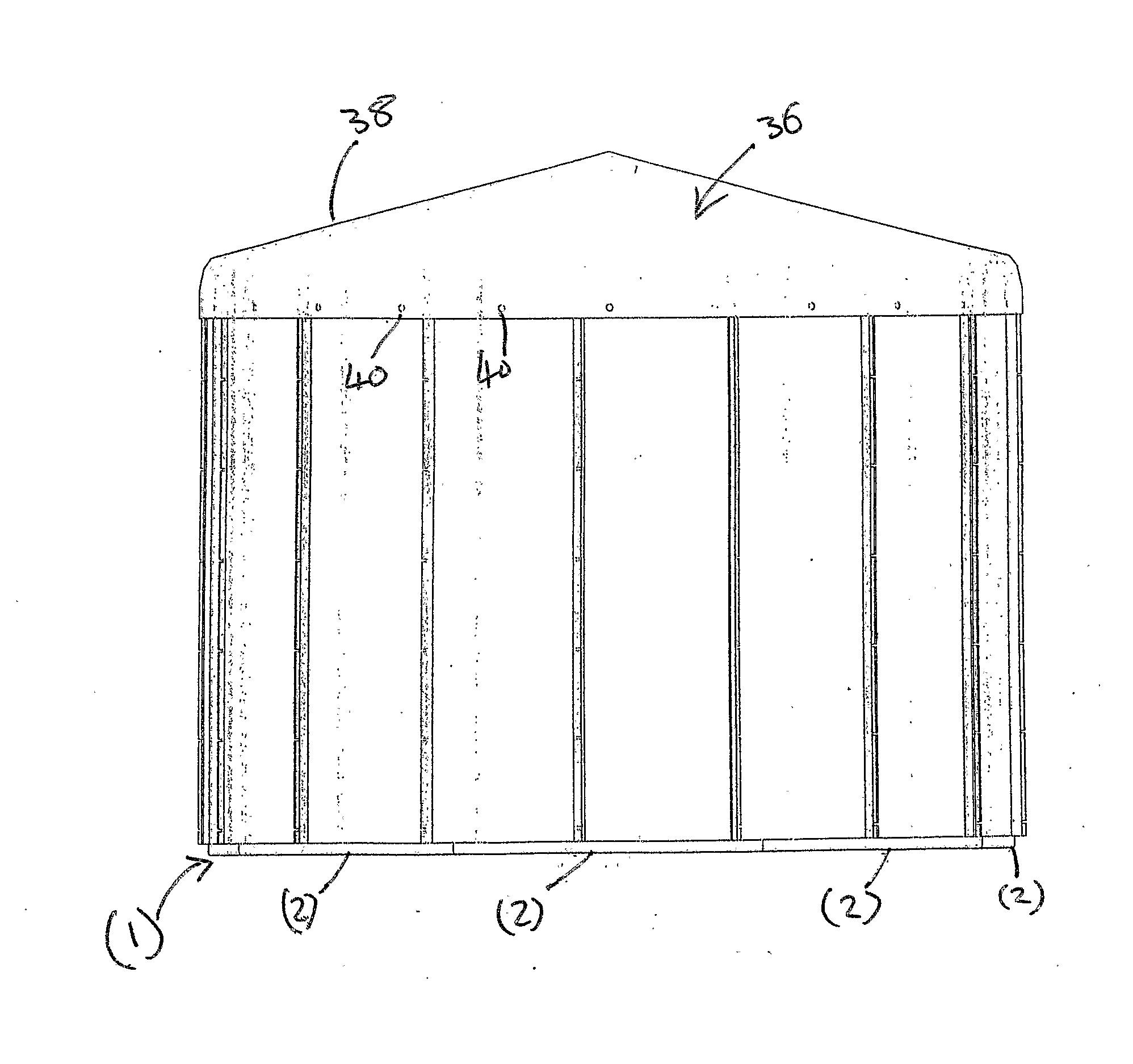
[0155]The present invention provides a multi-purpose demountable structure. The structure is shown as a tank (1) in its assembled form in FIG. 1. Reference is now made to the construction of the tank (1).

[0156]The tank (1) is sold as a kitset of parts. The components of the kitset are made from high density polyethylene plastic or similar materials. Alternatively the components of the present invention may be formed from aluminium, other plastic materials, or a combination of materials.

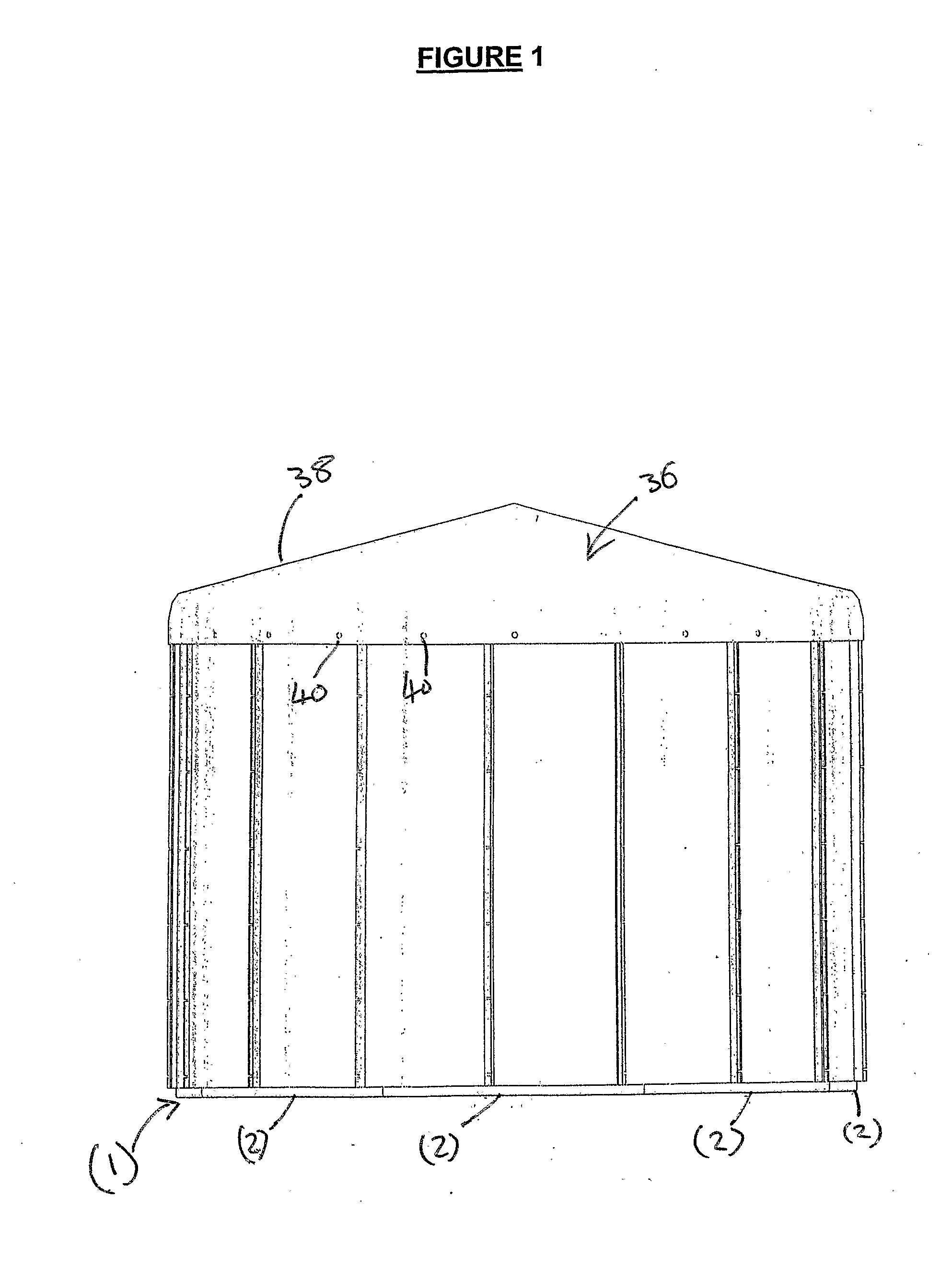
[0157]A base element (2) is shown in FIG. 2. The base element is formed from a member (3) having a substantially L shaped cross section. The member (3) has recesses (4 and 5) in each of its arms (6 and 7). FIG. 3 shows an end on view of the members (3). The member (3) has channels (8 and 9) in the recesses (4 and 5).

[0158]A floor panel (10) is inserted into the recess (4) so that it overlaps the end (11) of the member (3). The side edges (12, 13) of the floor panel (10) are shaped so that they can sit...


PUM

PropertyMeasurementUnit
lengthaaaaaaaaaa
flexibleaaaaaaaaaa
structureaaaaaaaaaa

Abstract

A method of constructing a structure, a structure constructed according to the method, and a kitset of parts. The structure may be a tank for holding liquids, or a temporary shelter for humans or animals.

Description

TECHNICAL FIELD[0001]The present invention relates to methods and apparatus for the construction of structures and in particular, the construction of tanks for the storage and processing of materials.BACKGROUND ART[0002]It is desirable in many situations to have a structure which can be easily constructed to hold substances or to provide temporary accommodation and housing for people and / or animals.[0003]Given the need and benefits offered by such structures, there are a number of different systems known providing various options.[0004]The traditional solution has been to transport preassembled or manufactured structures to the desired location. However, when a structure of large volume is required, this is often prohibitively costly as the volume of the structure significantly increases transport costs.[0005]One solution to this problem has been to provide demountable or collapsible structures.[0006]However, all suffer from inherent limitations including the intricate manner of the...

Claims


Application Information

Patent Timeline
Patent Type & Authority Applications(United States)
IPC IPC(8): B65D69/00B23P11/00
CPCB65D88/08B65D90/024B65D90/08Y10T29/49826E04H7/06E04H7/28E04B1/34315
Inventor PETERKEN, NEIL TERRY
Owner PETERKEN NEIL TERRY
Why Eureka
Try Eureka