Protected readout electrode assembly

a technology of readout electrodes and readout electrodes, which is applied in the direction of plastic/resin/waxes insulators, organic insulators, conductors, etc., can solve the problems of easy early aging, difficult manufacturing, and material resistivity properties that are righ

Inactive Publication Date: 2011-11-10
EUROPEAN ORGANIZATION FOR NUCLEAR RESEARCH
View PDF1 Cites 8 Cited by
  • Summary
  • Abstract
  • Description
  • Claims
  • Application Information

AI Technical Summary

Benefits of technology

[0010]The resistor pads serve as serial resistors in the electronic readout chain, permitting reliable signal propagation to the readout electrode assembly while at the same time protecting the readout pads and the readout electronics. The insulating layer formed on and / or between the readout pads reduces undesired coupling or crosstalk between neighboring readout pads.
[0038]According to the alternative embodiment, electron multiplication may take place in a plurality of holes extending through a foil with metal coatings on both sides. The generated electrons may then drift to the readout electrode assembly, which is not involved in the amplification process. Also according to the second detector design, a readout electrode assembly according to the present invention permits an efficient charge transport from the amplification gap to the readout pads while at the same time protecting the detector against sparks and discharges.DETAILED DESCRIPTION OF A PREFERRED EMBODIMENT

Problems solved by technology

However, finding a material with the right resistivity properties and still allowing easy manufacturing proved to be difficult.
Moreover, organic resistive layers that have conventionally been employed as cover layers are rather sensitive to sparks or discharges in the amplification gap, and hence prone to early aging when operated at high counting rates or high amplification fields.
Mineral resistive layers are more robust to sparks and discharges, but require complex manufacturing, and are hence less suitable for mass-production of large area detectors.
Sparks may not only damage the readout detector surface, but also inevitably lead to dead times during which events cannot be detected, hence reducing detector efficiency.

Method used


Image

  • Protected readout electrode assembly
  • Protected readout electrode assembly
  • Protected readout electrode assembly

Examples


first embodiment

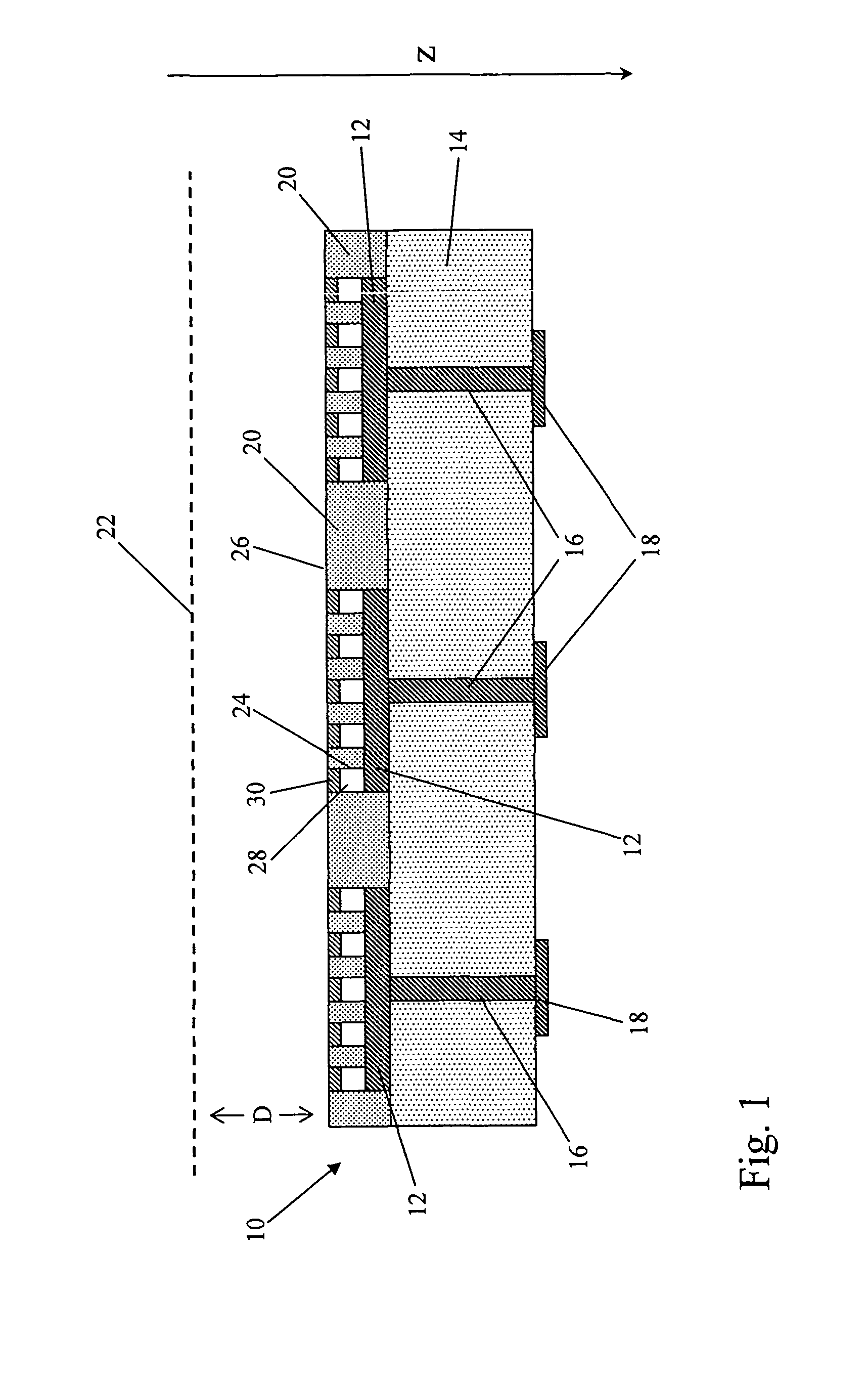
[0040]FIG. 1 is a schematic side view of a readout electrode assembly according to the present invention;

second embodiment

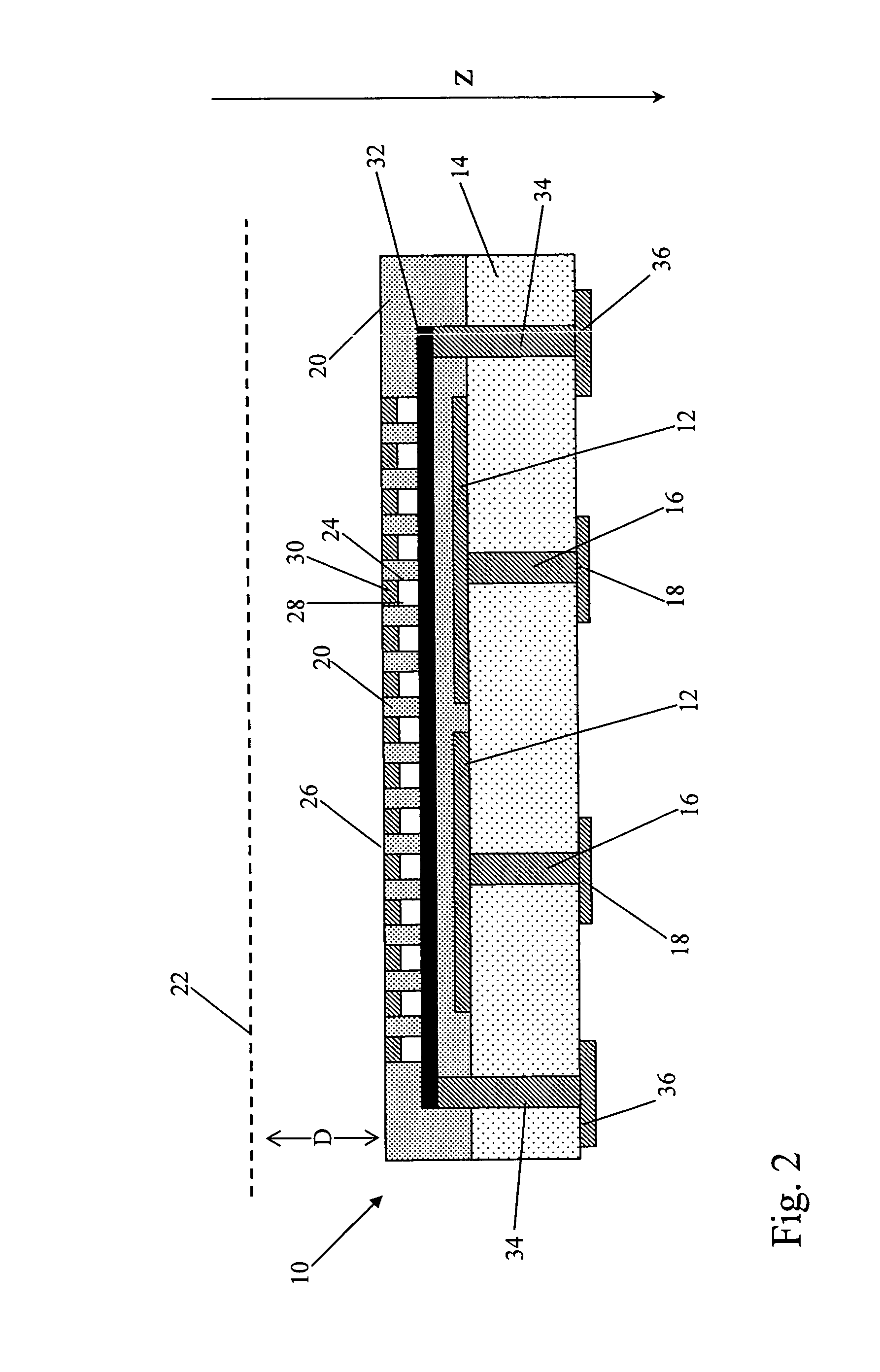
[0041]FIG. 2 is a schematic side view of a readout electrode assembly according to the present invention; and

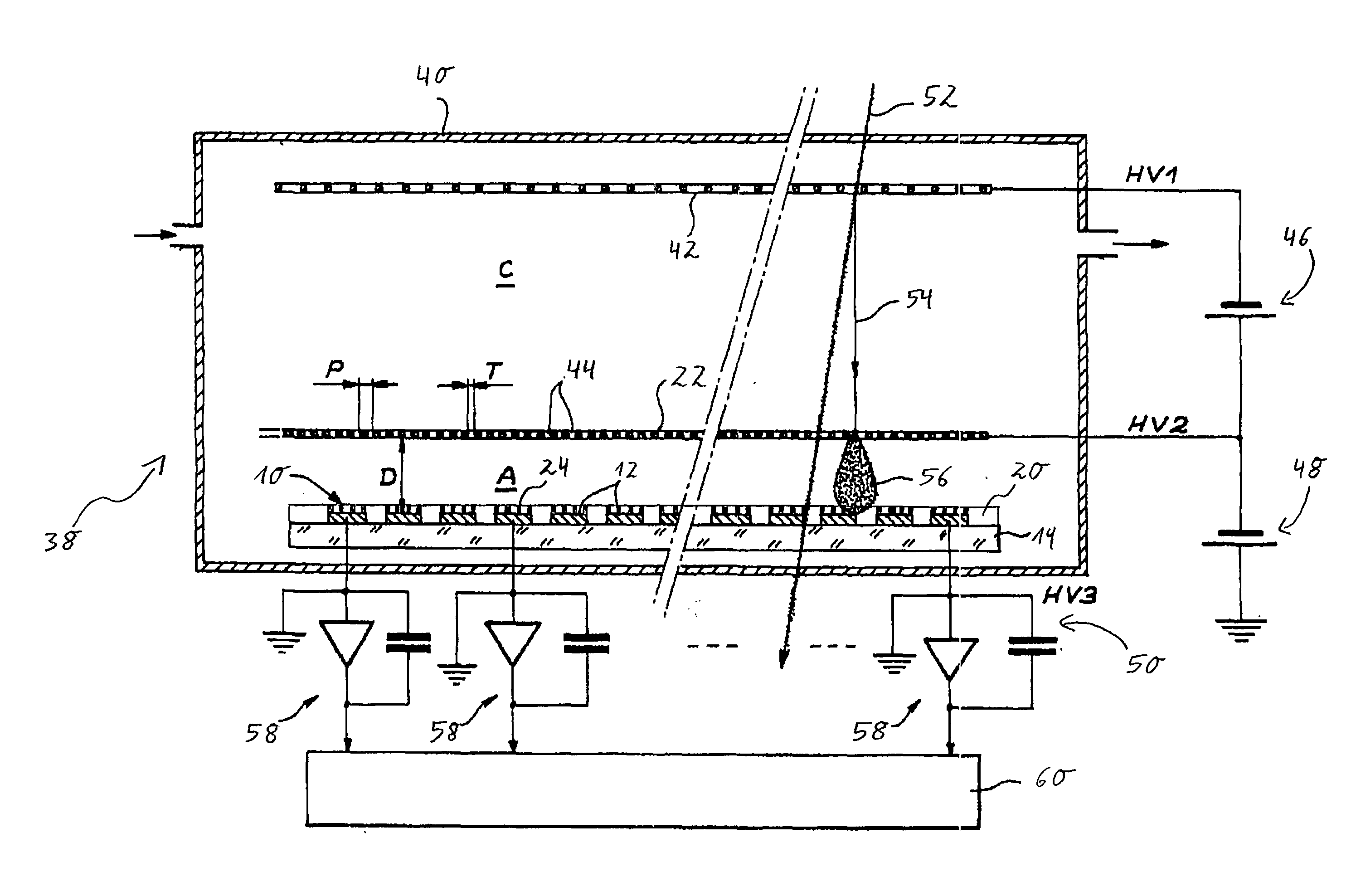
[0042]FIG. 3 is a schematic side view showing the operation of a readout electrode assembly according to the present invention in a Micromegas detector.

[0043]FIG. 1 illustrates a side view of a part of a readout electrode assembly 10 according to the present invention. Readout pads 12 are formed on the surface of a dielectric bulk substrate 14. In the embodiment shown in FIG. 1, the bulk substrate 14 is formed from flame retardant 4 (FR4), an epoxy resin bonded glass fabric, while the readout pads 12 are formed from copper. However, other materials may also be used for the readout pads 12 and for the bulk substrate 14. Metallic interconnectors 16 are embedded in the bulk substrate 14 and connect the readout pads 12 to connector plates 18 formed on the opposite surface of the bulk substrate 14. The connector plates 18 may in turn be connected to polarization means (not shown) ...


PUM

PropertyMeasurementUnit
distanceaaaaaaaaaa
resistanceaaaaaaaaaa
surface diameteraaaaaaaaaa

Abstract

The readout electrode assembly of an avalanche particle detector can be effectively protected against sparks and discharges by means of a plurality of resistor pads formed in a dielectric cover layer above the readout pads. The resistor pads may either be connected directly to the readout pads, or may be coupled capacitively by means of a charge spreading pad embedded into the dielectric cover layer and spatially separated from the readout pads. The charge spreading pad allows the distribution of charges to neighboring readout pads, and may hence increase the spatial resolution of the detector device.

Description

FIELD OF THE INVENTION[0001]The present invention relates to a readout electrode assembly for an avalanche particle detector, in particular for a micropattern gas detector (MPGD).BACKGROUND AND STATE OF THE ART[0002]Particle detectors are devices to detect, track and / or identify radiation or particles, and find wide applications throughout particle physics, biology as well as medical technology.[0003]Particle detectors exploiting the process of ionization and charge multiplication in gases have been in use with continued improvements ever since Rutherford first employed a gas-filled wire counter to study natural radioactivity in 1908. Methods for obtaining large stable proportional gains, increased resolution and greater robustness to sparks and discharges in gaseous detectors are a continuing subject of investigation in the detector community today.[0004]Gaseous detectors typically collect the electrons released by ionizing radiation and guide them to a region with a large electric...

Claims


Application Information

Patent Timeline
Patent Type & Authority Applications(United States)
IPC IPC(8): G01T1/18H01B7/00
CPCG01T1/185
Inventor DE OLIVEIRA, RUI
Owner EUROPEAN ORGANIZATION FOR NUCLEAR RESEARCH
Why Eureka
Try Eureka