Electrophotographic photoreceptor, and electrophotographic apparatus, process cartridge and method using the photoreceptor

a photoreceptor and electrophotography technology, applied in the direction of electrophotography process apparatus, instruments, corona discharge, etc., can solve the problems of increasing the mechanical load of the cleaning blade onto the contact plate of the photoreceptor, the method producing ozone or nitrogen oxides, and the environmental problems of ozone and nitrogen oxides, etc., to achieve uniform charge, efficient charge transport, and high quality

Inactive Publication Date: 2006-02-23
RICOH KK
View PDF25 Cites 0 Cited by
  • Summary
  • Abstract
  • Description
  • Claims
  • Application Information

AI Technical Summary

Benefits of technology

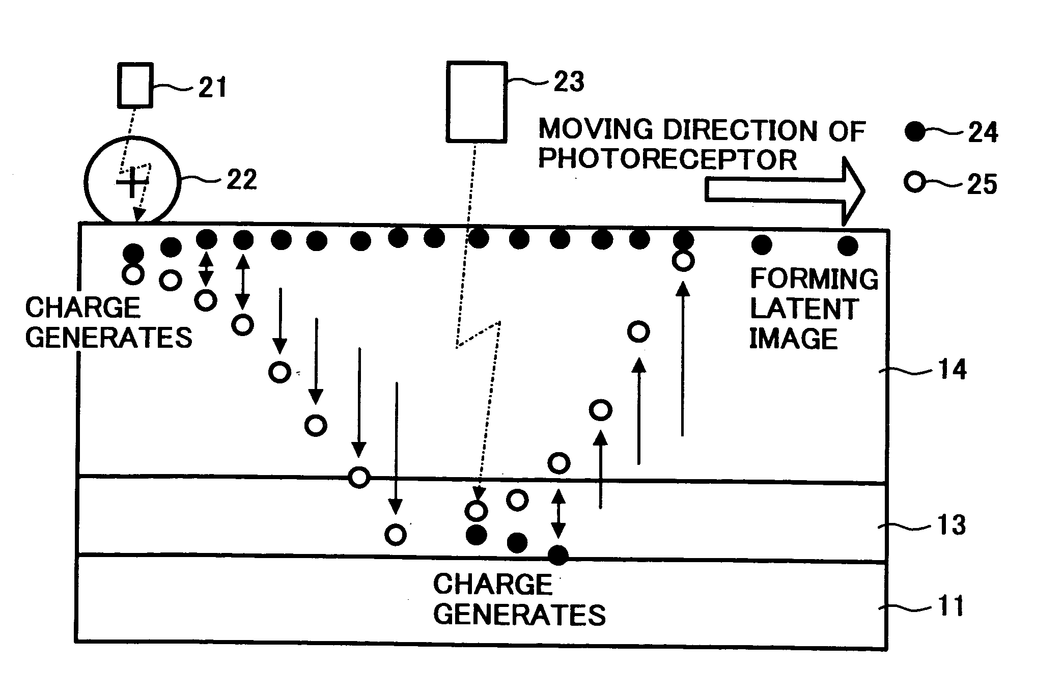
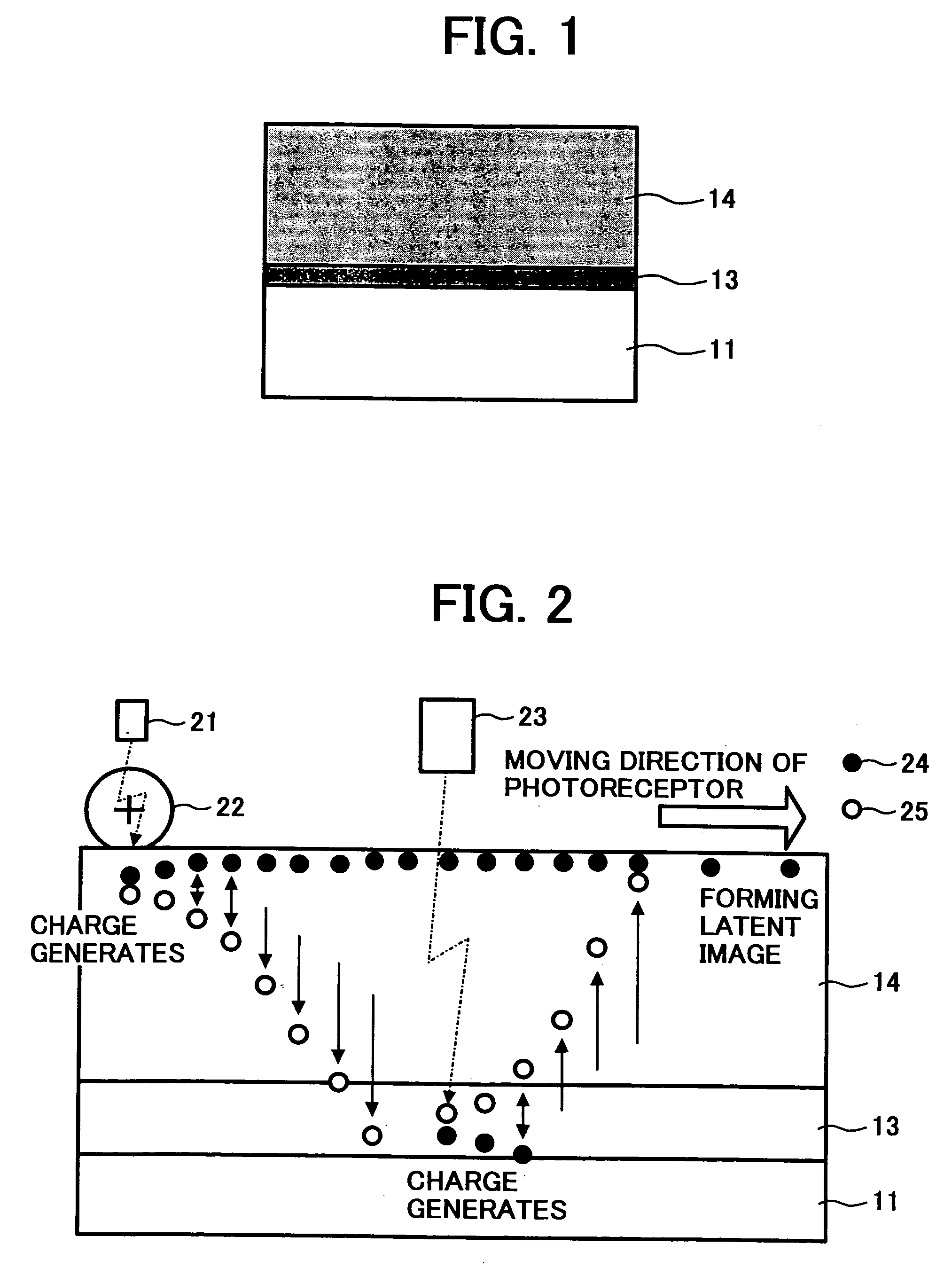
[0025] Accordingly, an object of the present invention is to provide an electrophotographic photoreceptor producing high quality images without producing ozone and nitrogen oxides when charged, and which is uniformly charged and has an efficient charge transport.

Problems solved by technology

In addition, the discharged products adhered on the photoreceptor typically increase the friction coefficient, resulting in an increase of a mechanical load by a cleaning blade onto a contact plate of the photoreceptor.
In addition, the ozone and nitrogen oxides are environmental problems as well.
However, this method produces ozone or nitrogen oxides because a high voltage is applied to the charge wire.
The products give an adverse effect not only on the environment but also the durability of the photoreceptor and the image quality produced thereby.
However, the discharge produces a small amount of ozone and nitrogen oxides.
However, the surface resistance of the photoreceptor largely changes due to an environment such as temperature and humidity, in which it is used, and the photoreceptor is not stably charged.
However, when the heater is installed, the total electric power consumption of the apparatus increases.
However, at present, a material that efficiently transports both of the positive and negative charges is not available.
In addition, because the same layer generates a charge when the photoreceptor is charged and when a latent image is formed in the single-layered photoreceptor, a time between the charge generation when the photoreceptor is charged and the charge generation when the latent image is formed is limited.

Method used


Image

  • Electrophotographic photoreceptor, and electrophotographic apparatus, process cartridge and method using the photoreceptor
  • Electrophotographic photoreceptor, and electrophotographic apparatus, process cartridge and method using the photoreceptor
  • Electrophotographic photoreceptor, and electrophotographic apparatus, process cartridge and method using the photoreceptor

Examples


example 1

[0144] On an aluminum substrate (outside diameter of 100 mm), the following undercoat layer coating liquid was coated by a dip coating method, and then dried to form an undercoat layer having a thickness of 3.5 μm.

[0145] (The undercoat Layer Coating Liquid)

Alkyd resin33(Bekkozol 1307-60-EL from Dainippon Ink& Chemicals, Inc.)Melamine resin2(Super Bekkamin G-821-60 from DainipponInk & Chemicals, Inc.)Titanium oxide (CR-EL from Ishihara20Sangyo Kaisha, Ltd.)Methyl ethyl ketone100

[0146] The following charge generation layer coating liquid including a oxotitaniumphthalocyanine pigment was coated on the undercoat layer by a dip coating method and then dried at 110° C. for 20 min to form a CGL having a thickness of 0.3 μm.

[0147] (The CGL Coating Liquid)

Oxotitaniumphthalocyanine pigment5Butyral resin2(S-lec BMS (from Sekisui Chemical Co.,80Ltd.) Tetrahydrofuran

[0148] The following CGTL coating liquid including a low molecular weight charge transport material and a bisazo charge gener...

example 2

[0156] The procedures of preparation for an electrophotographic photoreceptor and evaluations thereof in Example 1 were repeated except for forming a surface protection layer on the CGTL using the following plasma CVD apparatus.

[0157] An electrophotographic photoreceptor prepared by the procedures in Example 1 was set in a plasma CVD apparatus as shown in FIGS. 13 to 15 to form a surface protection layer on the photoreceptor. In FIG. 13, numeral 107 is a vacuum chamber of the plasma CVD apparatus, and is separated from a load / unload spare room 117 by a gate vale 109. The vacuum chamber 107 is vacuum pumped by an exhaust system formed of a pressure control valve 121, a turbo molecular pump 122 and a rotary pump 123, and therefore a certain pressure is maintained in the chamber. The vacuum chamber 107 includes a reaction chamber 150. The reaction chamber is formed of a frame constitute 102 as shown in FIGS. 14 and 15 (having a quadrangular or hexagonal shape when seen from an electri...

example 3

[0163] The procedures of preparation for an electrophotographic photoreceptor and evaluations thereof in Example 1 were repeated except for forming a surface protection layer having the following components and a thickness of 4 μm on the CGTL.

[0164] (A Surface Protection Layer Coating Liquid)

Bisphenol Z type polycarbonate6Fine particles of alumina3(AA03 from Sumitomo Chemical Co., Ltd.)Tetrahydrofuran110Cyclohexanone60

[0165] The initial image had a good background, black solid image and halftone image.

[0166] As a result of the running image (A4 having a 7% image area) production, the chargeability of the photoreceptor did not deteriorate and the image quality was good even after 500,000 images were produced. Then, an abrasion amount of the surface protection layer of the photoreceptor was 1.9 μm.


PUM


Abstract

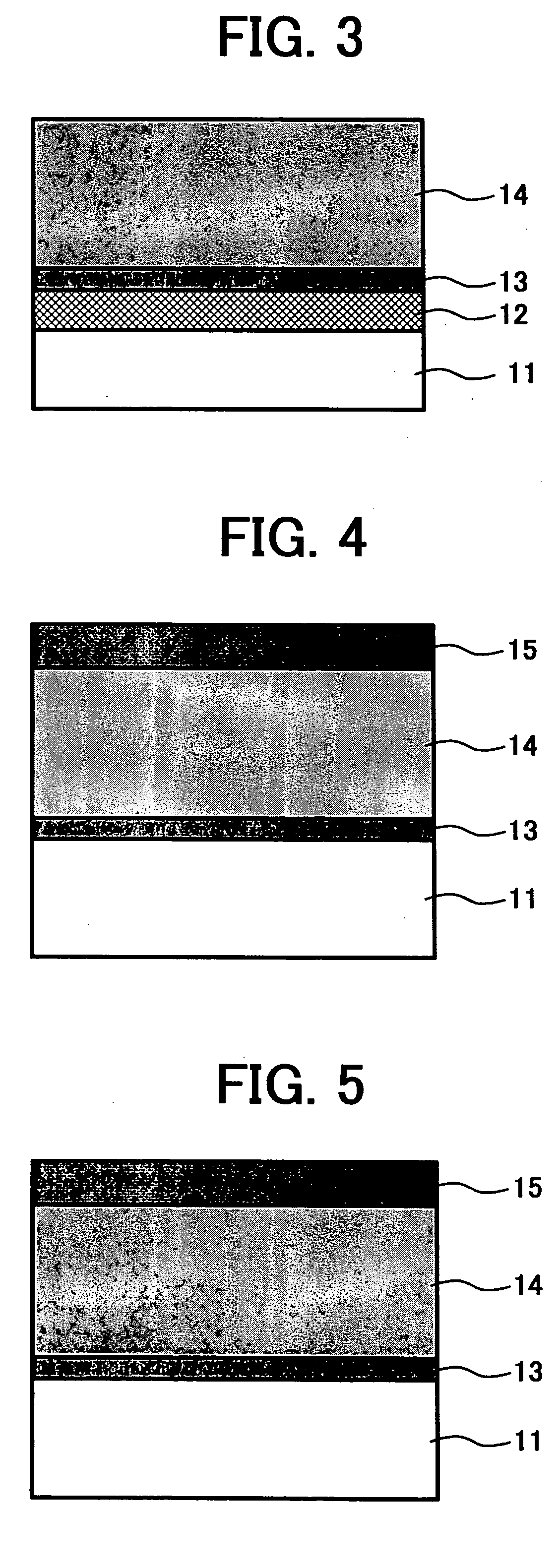
An electrophotographic photoreceptor including an electroconductive substrate, a charge generation layer overlying the electroconductive substrate to generate a first charge to form an electrostatic latent image when exposed to a first light, and a charge generation and transport layer overlying the charge generation layer to generate a second charge when exposed to second light and to transport the first and second charges to a surface of the photoreceptor.

Description

BACKGROUND OF THE INVENTION [0001] 1. Field of the Invention [0002] The present invention relates to an electrophotographic photoreceptor, and an electrophotographic apparatus, process cartridge and method using the photoreceptor. [0003] 2. Discussion of the Background [0004] An electrophotographic method is typically one of an image forming method of charging a photoconductive photoreceptor in a dark place with, e.g., a corona discharge; irradiating the photoreceptor with imagewise light; forming an electrostatic latent image thereon by selectively scattering a charge on the irradiated part thereon; and developing the latent image with a toner including a colorant such as dyes and pigments and a binder such as polymers to form a visual toner image. [0005] In such an electrophotographic method, the photoreceptor requires the following basic properties: [0006] (1) the photoreceptor can be charged so as to have a proper potential in a dark place; [0007] (2) the charge scarcely scatter...

Claims


Application Information

Patent Timeline
Patent Type & Authority Applications(United States)
IPC IPC(8): G03G5/047G03G5/043G03G7/00
CPCG03G5/043G03G7/0033G03G5/047
Inventor IKUNO, HIROSHITSUKAMOTO, TAKEO
Owner RICOH KK
Why Eureka
Try Eureka